Combining SCR with PNA for Low Temperature Emission Control

a technology of low temperature emission control and combining scr, which is applied in the direction of machines/engines, physical/chemical process catalysts, separation processes, etc., can solve the problems of difficult to address, reduce and relatively inefficient systems below operating temperature. , to achieve the effect of reducing the concentration of nox and reducing the concentration of stored nox

Active Publication Date: 2016-05-19
JOHNSON MATTHEY PLC
View PDF43 Cites 74 Cited by
  • Summary
  • Abstract
  • Description
  • Claims
  • Application Information

AI Technical Summary

Benefits of technology

[0022]In yet another aspect of the invention, a method for reducing the concentration of NOx in an exhaust gas stream during the cold start of the engine comprises contacting an exhaust gas stream containing NOx with a catalyst article comprising an SCR catalyst and a NOx adsorber catalyst as described herein, storing NOx in the catalyst article during cold engine startup, and reducing stored NOx by hydrocarbon SCR.

Problems solved by technology

The reduction of NOx to N2 is particularly problematic because the exhaust gas contains enough oxygen to favor oxidative reactions instead of reduction.
However, these systems are relatively inefficient below their operating temperature (the “cold start” period).
NOx conversion below 180° C. is difficult to address using the current systems, and future European and US legislation will stress the low temperature NOx conversion.
The low temperature NOX emission can be controlled by heating strategies but this has a detrimental effect of CO2 emissions.
As even more stringent national and regional legislation lowers the amount of pollutants that can be emitted from diesel engines, reducing emissions during the cold start period is becoming a major challenge.

Method used


Image

  • Combining SCR with PNA for Low Temperature Emission Control
  • Combining SCR with PNA for Low Temperature Emission Control
  • Combining SCR with PNA for Low Temperature Emission Control

Examples


example 1

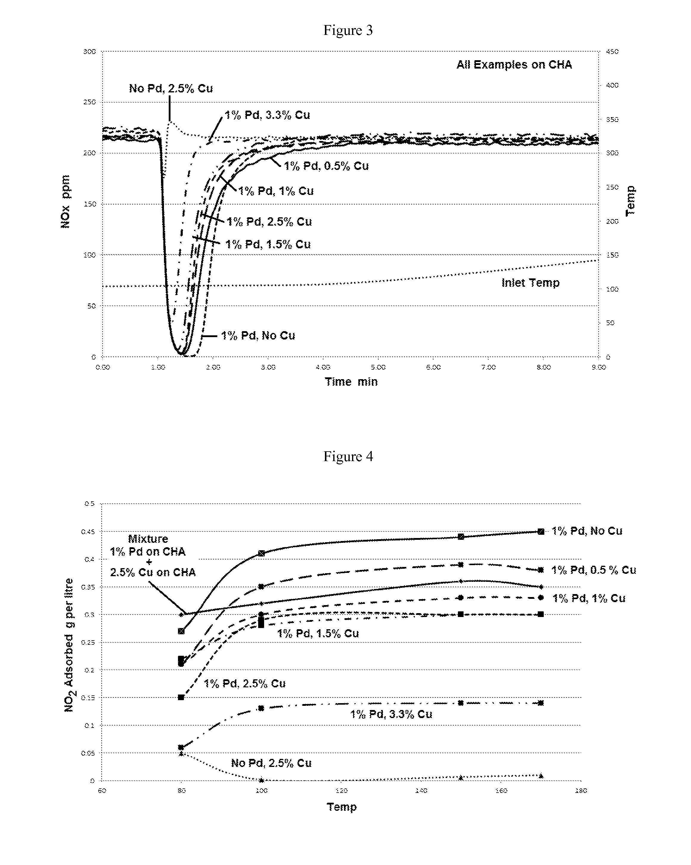
Powder Samples with Fixed Pd of 1 wt % and Varying Cu Loading on CHA

[0116]A series of catalysts comprising copper and / or palladium containing aluminosilicate chabazites (CHA with a SAR ratio of 25) were prepared by incipient wetness impregnation using copper acetate and palladium nitrate solutions, with copper and palladium loadings shown in the table below. Comparative Catalysts 6 and 7 were each a single component only comprising Pd CHA or Cu CHA, respectively.

One ComponentComparative Catalyst 6:1 wt. % Pd CHAComparative Catalyst 7:2.5 wt. % Cu CHA

[0117]Each of Catalysts 8-12 below had two components, with the first component comprising Cu CHA in the amounts indicated below and the second component comprising 1 wt. % Pd. The Cu component was first impregnated on the chabazite and calcined before the impregnation of the given concentration of the Pd component. After drying at 100° C., the samples are calcined at 500° C. The samples were then hydrothermally aged at 750° C. in an air...

example 2

Powder Samples with Fixed Cu Loading and Varying Pd

[0123]A series of catalysts comprising copper and / or palladium containing aluminosilicate chabazites (CHA SAR) were prepared as described in Example 2 with a fixed Cu loading of 2.5 wt. % copper and varying palladium loadings between 0.2 wt. % to 1 wt. % shown in the table below. Comparative Catalyst 7, described above, was a single layer comprising a 2.5% Cu CHA. Each of Catalysts 13-15 below had two components, comprising 2.5% Cu CHA with Pd in the amounts indicated below.

Second Component with fixed Cu at 2.5 wt. %Catalyst 130.2 wt. % PdCatalyst 140.5 wt. % PdCatalyst 151.0 wt. % Pd

[0124]The samples were analyzed for their PNA and SCR activities as described above in Example 1. FIG. 7 shows the amount of NOx present in the gas over time. The graph shows a reduction in the concentration of NOx from about 1 minute to about 2 minutes. The greater the decrease in the NOx concentration and the length of time of the decrease, the higher...

example 3

Coated Monolith

[0127]A series of catalysts comprising copper or palladium containing aluminosilicate chabazites (CHA) having an SAR of 25 were prepared. The Cu loading was 2.5 wt. % and the Pd loading was 1 wt. %. Each of the catalysts was calcined at 500° C. and then milled to a D90 of about 5 μm. The milled samples were then slurried into a washcoat before coating on a monolith substrate with the Pd CHA as the bottom layer and the Cu chabazite as the top layer at the washcoat loadings shown in the table below for catalysts 3-5. Comparative Catalyst 1 was a single layer comprising Cu CHA at a loading of 2.5 wt. % and washcoat loading of 2.5 g in3. Comparative Catalyst 2 was a two layer catalyst with the upper layer comprising Cu CHA at a washcoat loading of 2.5 g in3 and the lower layer comprising ZnO at a loading of 2 g per in3. The samples were then calcined in air at 500° C.

Top LayerBottom LayerCatalyst 32.5 g / in3 Cu CHA1.5 g / in3 Pd CHACatalyst 41.5 g / in3 Cu CHA1.5 g / in3 Pd CHAC...


PUM

PropertyMeasurementUnit
concentrationaaaaaaaaaa
total weightaaaaaaaaaa
weightaaaaaaaaaa

Abstract

A catalyst article comprises an SCR catalyst and a NOx adsorber catalyst, where each of these catalysts comprise a metal molecular sieve, each with a different metal. The catalyst article can be close coupled with other components to give a NOX performance advantage from cold start to a combined DOC and SCRF system. Higher NOX conversion is also shown in under-floor location due to NOx storage before SCR light off and selective NH3 slip control, allowing higher NH3 fill levels. Systems comprising the catalyst article and methods of using the catalyst article to give improved hydrocarbon and carbon monoxide control, as well as ammonia slip control, are described. The systems can include flow-through or wall-flow monoliths.

Description

FIELD OF THE INVENTION[0001]The present invention is directed towards the use of catalytic articles comprising a selective catalytic reduction (SCR) catalyst and a passive NOX adsorber catalyst. These catalysts can be arranged in a layered system with a bottom layer comprising palladium on ceria or a metal zeolite acting as a NOX adsorber catalyst and which can also provide ammonia slip control as well as hydrocarbon (HC) and carbon monoxide (CO) conversion and the top layer containing the SCR catalyst. Alternatively these catalysts can be zoned or can be combined in a single washcoat.BACKGROUND OF THE INVENTION[0002]Combustion of hydrocarbon-based fuel in engines produces exhaust gas that contains, in large part, relatively benign nitrogen (N2), water vapor (H2O), and carbon dioxide (CO2). But the exhaust gases also contains, in relatively small part, noxious and / or toxic substances, such as carbon monoxide (CO) from incomplete combustion, hydrocarbons (HC) from un-burnt fuel, nitr...

Claims


Application Information

Patent Timeline
Patent Type & Authority Applications(United States)
IPC IPC(8): B01J29/76B01D53/94B01J29/74
CPCB01J29/763B01J29/743B01D53/9418B01D2255/20761B01D53/9477B01D2255/50B01D2255/1021B01D53/9422B01D53/9468B01D2251/2062B01D2255/2065B01D2255/1023B01D2255/91B01D2258/012B01D2257/404Y02A50/20Y02T10/12B01D53/9472F01N3/0814F01N3/0842F01N3/2066B01D53/94
Inventor PHILLIPS, PAUL RICHARDCHANDLER, GUY RICHARDGREEN, ALEXANDER NICHOLAS MICHAELHARRIS, MATTHEW EBENWYLIE, JAMES ALEXANDERGALL, MIROSLAWBURGESS, GARRY ADAM
Owner JOHNSON MATTHEY PLC
Why Eureka
Try Eureka