Optically transparent composite film for display and manufacturing method therefor
a composite film and optically transparent technology, applied in the field of optically transparent composite films for display, can solve the problems of poor moisture and oxygen barrier ability of polymer transparent films, difficult application as flexible substrates, and lack of shock resistance, so as to improve the adhesion, flexible display, and improve the effect of gas barrier properties
- Summary
- Abstract
- Description
- Claims
- Application Information
AI Technical Summary
Benefits of technology
Problems solved by technology
Method used
Image

Examples
example 1
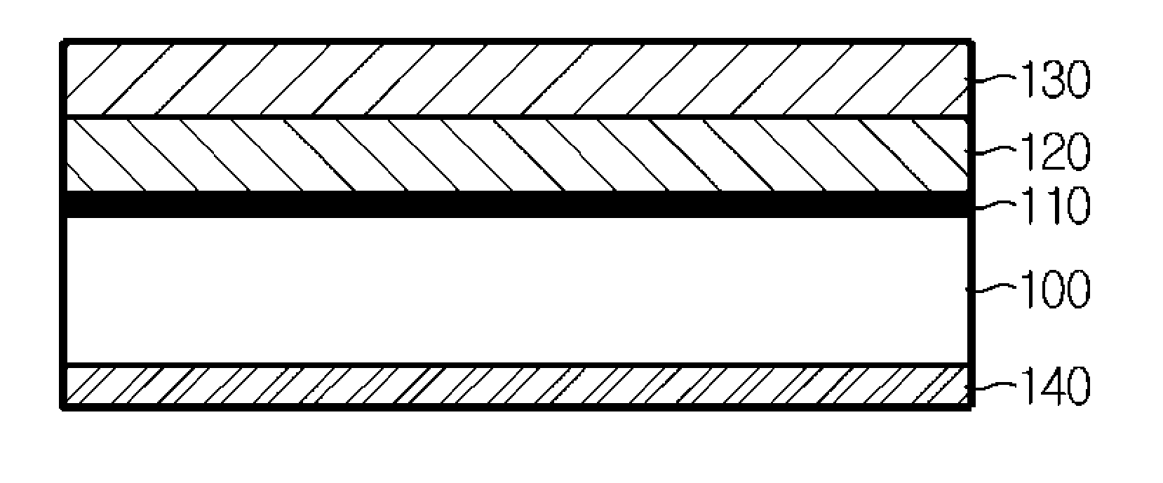
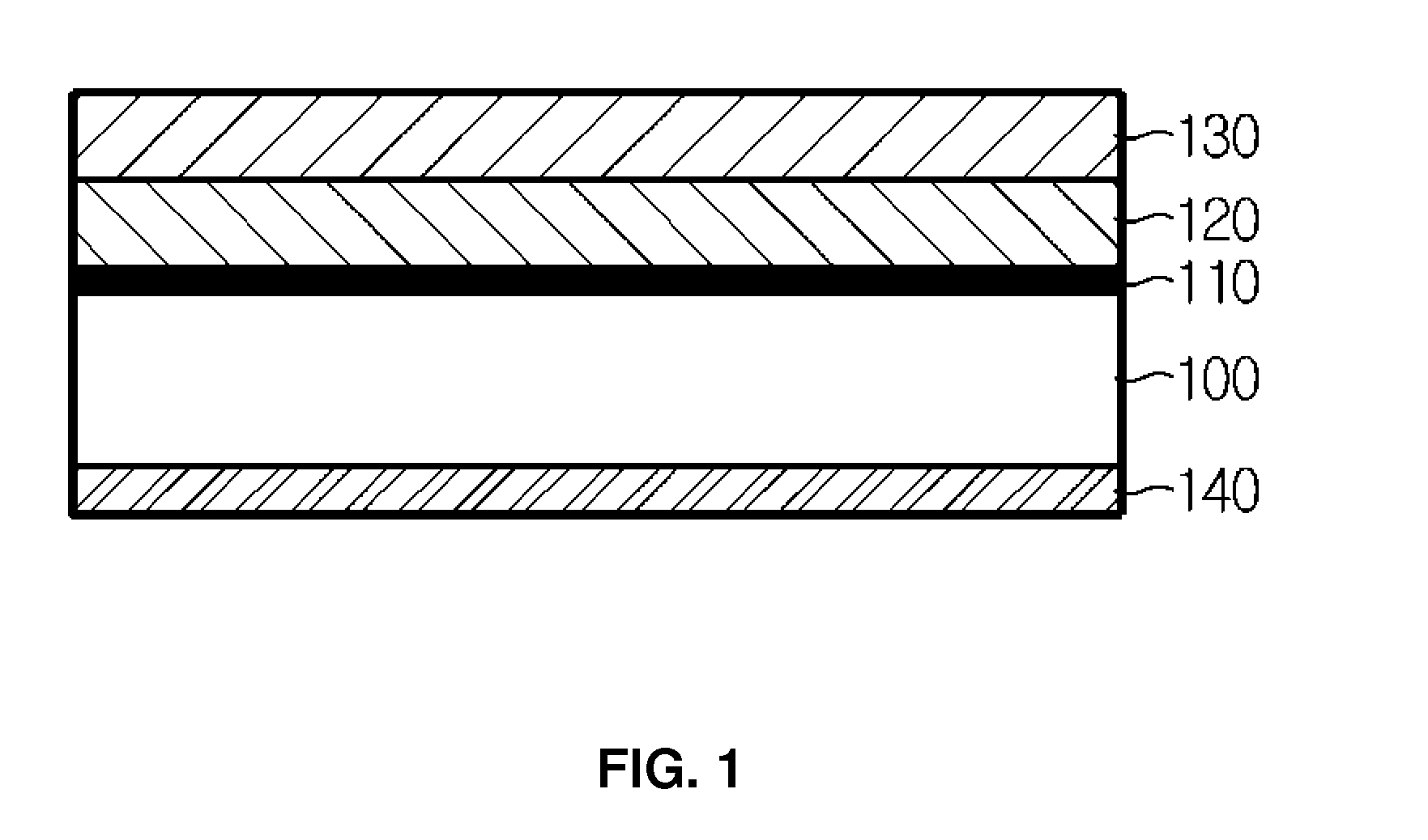
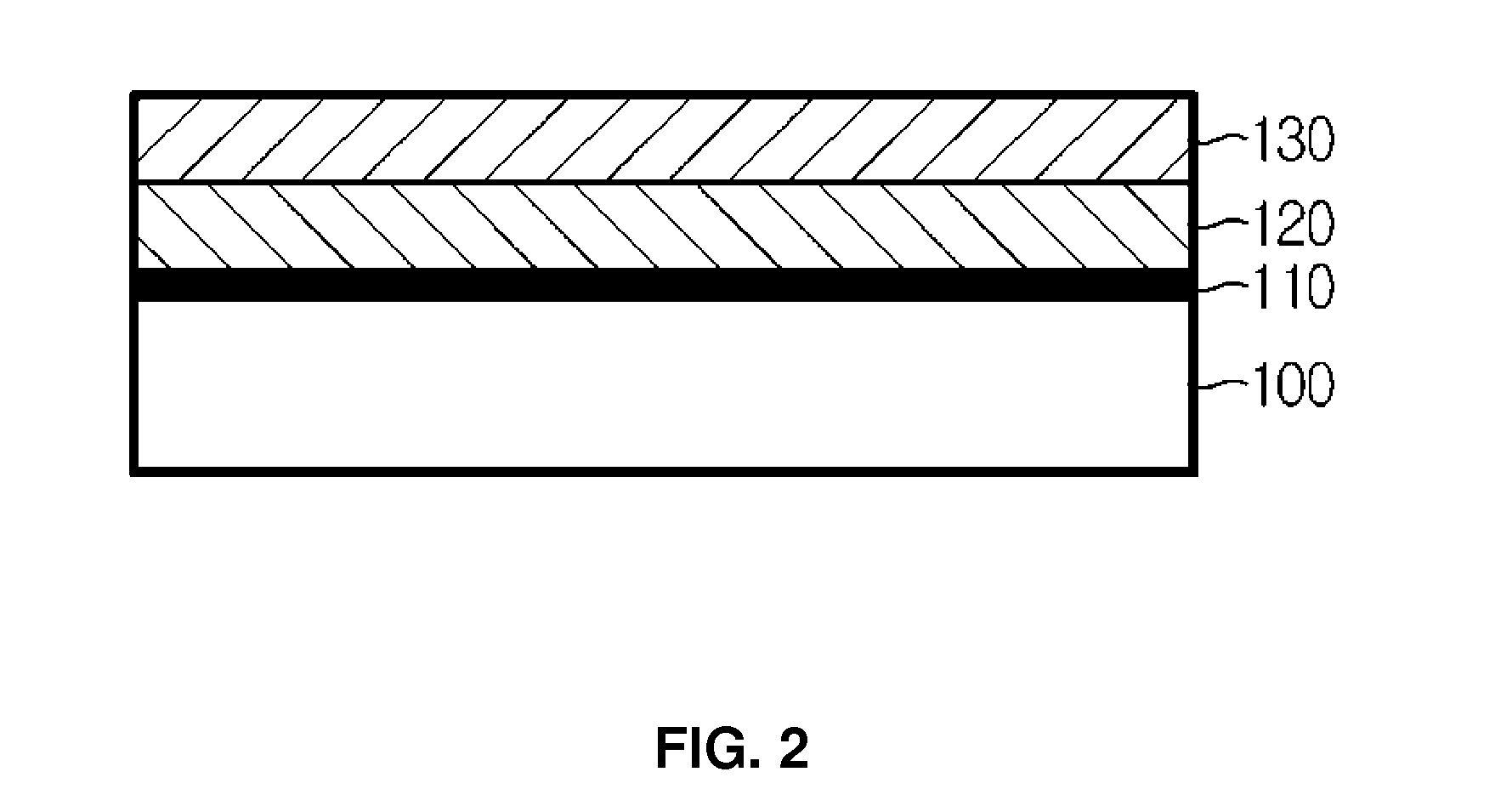
[0077]A 50 μm thick polyethylene terephthalate (PET) transparent film (Model name: SH34) made by SKC was used as a transparent plastic film which serves as a substrate. The plastic film was subjected to reaction at a rate of 2.7 M / min using a roll-to-roll sputter dual mode tool including six coating zones and a plasma treatment zone as shown in FIG. 4 by applying the power of 0.5 W / cm2 to an electrode to generate a plasma while maintaining a degree of vacuum at 2 mtorr with oxygen gas being fed at 60 sccm (Standard Cubic Centimeter per Minute; 0° C., an amount at 1 atmospheric pressure) into the plasma treatment zone. Subsequently, silicon targets were mounted in a first coating zone and a second coating zone, and argon and nitrogen gas was each injected at a ratio of Ar:N2=150:60, so a silicon nitride film was deposited on a plasma surface treatment layer with the power of 8.8 W / cm2 at a rate of 1 M / min. In SEM observation, the silicon nitride film was found 30 nm thick.
[0078]To fo...
example 2
[0089]To compare the plasma effect, the surface roughness of a 50 μm thick cyclo olefin plastic (COP) film (made by ZEON CORPORATION) plasma-treated by the same method as Example 1 was measured.
experimental example
[0091]For the optically transparent composite films of Example 1 and Comparative examples 1 through 3 manufactured by the above method, a vapor transmission rate, an oxygen transmission rate, a light transmittance, haze, scratch resistance, adhesion, and a rear surface energy of a polymer substrate were measured by the following evaluation method, and their results are shown in Table 1.
[0092]Also, to directly compare the plasma treatment effect, surface analysis results of Example 2 and Comparative example 4 are shown in Table 2.
[0093]1) Vapor transmission rate: measurement was made under 37.8° C. / RH100% for 48 hours using Mocon PERMATRAN-W3 / 31.
[0094]2) Oxygen transmission rate: measurement was made under 35° C. RH0% using Mocon OX-TRAN 2 / 20.
[0095]3) Light transmittance: measurement was made according to ASTM D1003 using Minolta 3600D.
[0096]4) Haze: measurement was made according to ASTM D1003 using Nippon Denshoku NDH-5000.
[0097]5) Scratch resistance: scratch resistance was measure...
PUM
| Property | Measurement | Unit |
|---|---|---|
| vapor transmission rate | aaaaa | aaaaa |
| Ra | aaaaa | aaaaa |
| thickness | aaaaa | aaaaa |
Abstract
Description
Claims
Application Information
 - R&D
- Intellectual Property
- Life Sciences
- Materials
- Tech Scout
- Unparalleled Data Quality
- Higher Quality Content
- 60% Fewer Hallucinations
Browse by: Latest US Patents, China's latest patents, Technical Efficacy Thesaurus, Application Domain, Technology Topic, Popular Technical Reports.
© 2025 PatSnap. All rights reserved.Legal|Privacy policy|Modern Slavery Act Transparency Statement|Sitemap|About US| Contact US: help@patsnap.com