
Processing method and image processing apparatus

a processing method and image processing technology, applied in the field of image processing methods and image processing apparatuses, can solve the problems of increasing the cost of the apparatus, the lens system controlling the diameter of the irradiation spot, and the time required for image recording and image erasure is long, so as to reduce the time taken, save space, and high-speed image rewriting

Active Publication Date: 2016-09-29
RICOH KK
View PDF2 Cites 5 Cited by
  • Summary
  • Abstract
  • Description
  • Claims
  • Application Information

AI Technical Summary

Benefits of technology

The present invention provides an image processing apparatus that can solve conventional problems and achieve high speed image rewriting and space saving with one image processing apparatus. Additionally, it can reduce the time taken to switch from image erasing to image recording and achieve high-quality images, improved repetition durability, and barcode readability.

Problems solved by technology

However, there is a problem that a time required for image recording and image erasing is long due to jumps between respective lines to be drawn, and wait times.
This proposed method enables recording of a high-quality image by controlling the irradiation energy even with respect to minute undulations, but necessitates highly precise control to bring about a problem that the cost of the apparatus will be expensive.
However, this proposal has a problem that the lens system for controlling the irradiation spot diameter will be complicated to raise the cost of the apparatus.
However, it takes time to shift from image erasing to image recording, and it has been unable to perform image rewriting at high speed.
However, with this proposal, it is difficult to switch the beam diameter at high speed per dot, and partial erasing may leave unerased portions if it is by rewriting per dot.
Therefore, there are problems regarding image rewriting at high speed, and securement of image erasing performance.
However, with this proposal, it takes time to move the image processing apparatus or the thermally reversible recording medium, and it is difficult to perform rewriting at high speed.
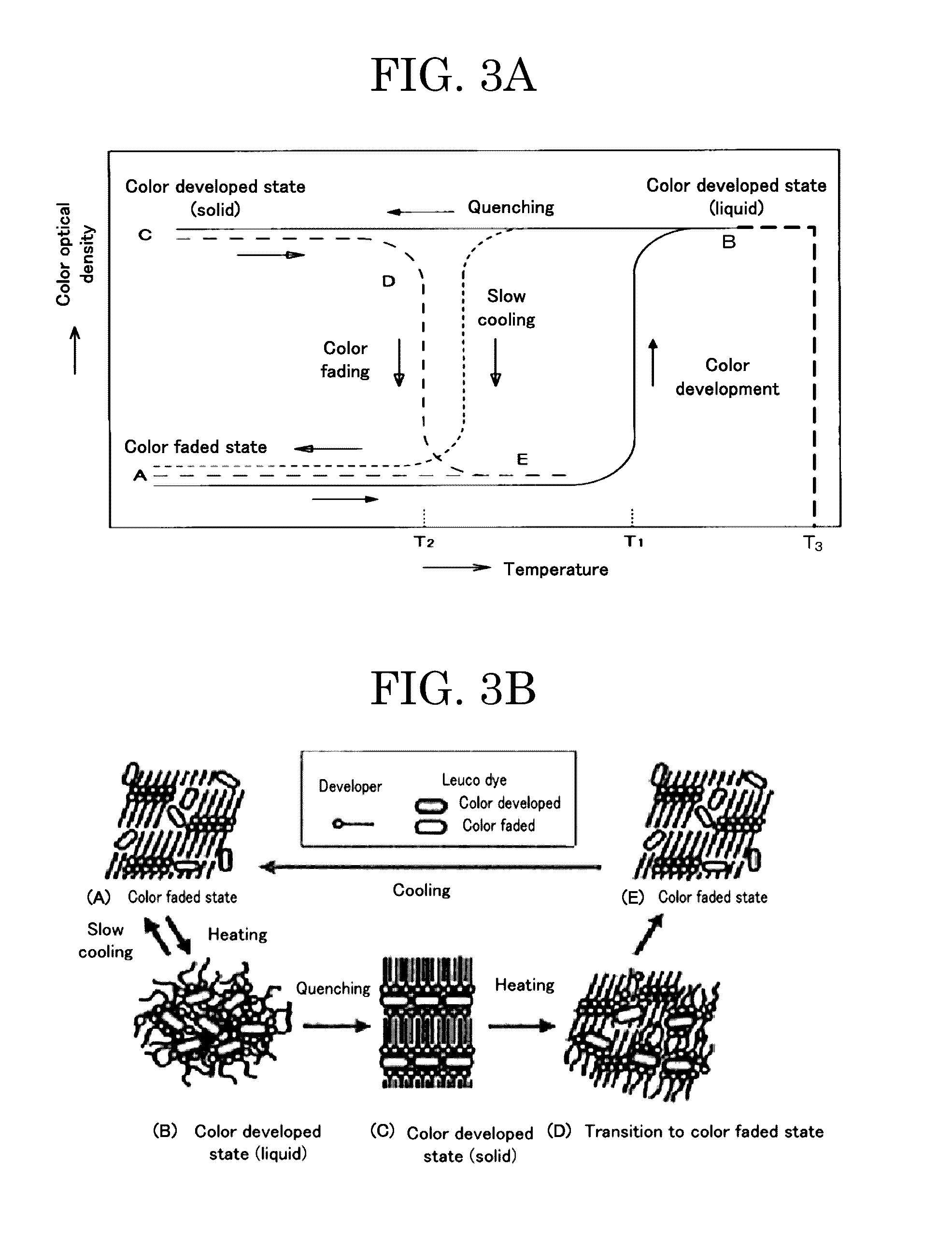
At this time, heat applied to the thermally reversible recording medium for erasing the image accumulates, and this heat dissipates at short time scales.
When laser light irradiation is employed as a method for applying heat, the time at which heat is applied varies from region to region within the thermally reversible recording medium, and the temperature of the thermally reversible recording medium therefore becomes non-uniform.
If an image is recorded onto the thermally reversible recording medium on which the temperature is non-uniform, quenching of the thermally reversible recording layer is inhibited to thereby cause problems such as degradation of the density of an image to be drawn and degradation of repetition durability, and a region having a high temperature will be under excessive heat during image recording when an image is recorded onto the thermally reversible recording medium on which the temperature is non-uniform with a fixed laser output, to thereby thicken the line width, collapse characters and symbols, degrade the image density, and reduce readability of an information code and repetition durability.
However, in terms of speeding up the erasing step, not only a time during which to reach the aimed temperature but also a heating time for which the aimed temperature is maintained are necessary for erasing, and it is impossible to realize high speed erasing only by raising the irradiation power.
However, there are problems regarding high speed recording, and degradation of repetition durability due to damages to the thermally reversible recording medium depending on the position thereof at which it is to be irradiated with laser light having high energy density because the beam diameter becomes small when the focal length is at the position.

Method used


Image

  • Processing method and image processing apparatus
  • Processing method and image processing apparatus
  • Processing method and image processing apparatus

Examples


manufacture example 1

Manufacture of Thermally Reversible Recording Medium

[0264]A thermally reversible recording medium of which color tone changes reversibly due to heat was manufactured according to the method described below.

-Support Member-

[0265]A white polyester film (TETORON (Registered Trademark) FILM U2L98W manufactured by Teijin DuPont Films Japan Limited) having an average thickness of 125 μm was prepared as the support member.

-Formation of First Oxygen Barrier Layer-

[0266]A urethane-based adhesive (TM-567 manufactured by Toyo-Morton, Ltd.) (5 parts by mass), isocyanate (CAT-RT-37 manufactured by Toyo-Morton, Ltd.) (0.5 parts by mass), and ethyl acetate (5 parts by mass) were stirred well to thereby prepare an oxygen barrier layer coating liquid.

[0267]Next, a silica-vapor-deposited PET film (TECHBARRIER HX manufactured by Mitsubishi Plastics, Inc., oxygen permeability: 0.5 mL / m2 / day / Mpa) was coated with the oxygen barrier layer coating liquid with a wire bar, and heated and dried at 80° C. for ...

example 1

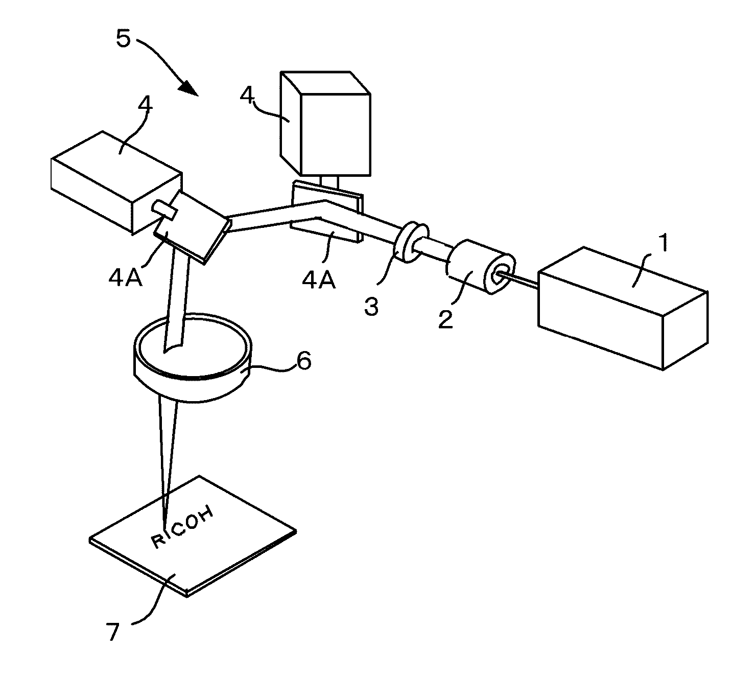
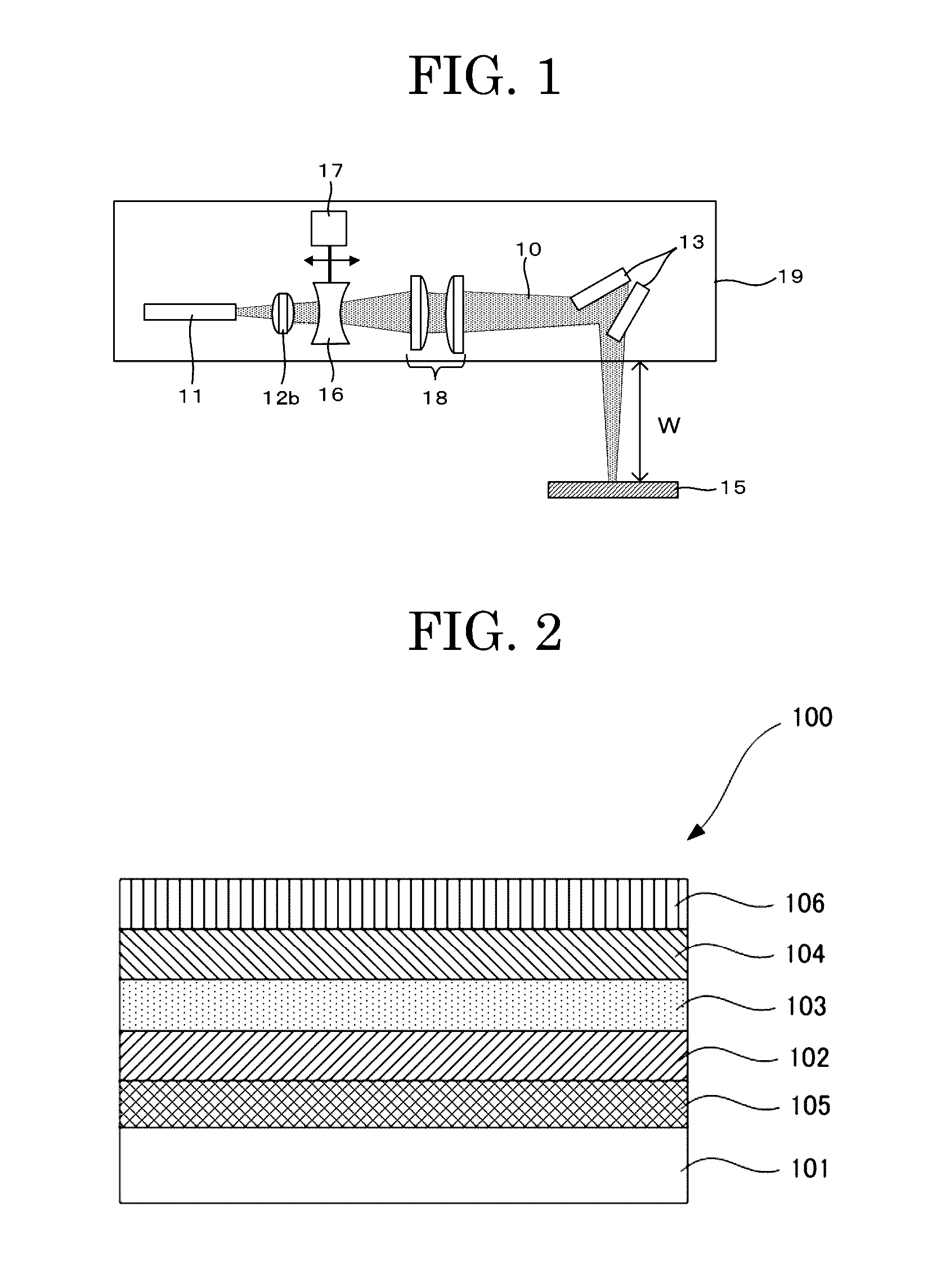
[0278]The thermally reversible recording medium of Manufacture Example 1 was used, and as shown in FIG. 1, an optical system was formed by arranging a fiber-coupled LD (laser diode) light source (PLD 60 manufactured by IPG Photonics Corporation, central wavelength: 974 nm, maximum power output: 60 W) as the laser light source 11, arranging the collimator lens 12b immediately after the fiber for collimating the beam to parallel light, and arranging the focal length control unit 16 and the condensing lens 18. After this, image processing was performed with a LD marker apparatus that was configured to irradiate the thermally reversible recording medium with laser light by scanning the laser light with a galvano scanner 6230H manufactured by Cambridge Inc.

[0279]The thermally reversible recording medium was fixed with the LD marker apparatus such that the work distance from the surface of the optical head to the thermally reversible recording medium would be 150 mm, and the beam diameter...

example 2

[0288]Image recording was performed under the same conditions as Example 1, except that the medium position was set at the work distance of 147 mm unlike Example 1, and barcode grade valuation was performed. The results are shown in Tables 1.


PUM


Abstract

Provided is an image processing apparatus configured to perform by itself image erasing and image recording to a thermally reversible recording medium by irradiating it with laser light and heating it, including a laser light emitting unit, a laser light scanning unit, a focal length control unit, and an information setting unit. During image erasing, the focal length control unit performs control to defocus at the position of the thermally reversible recording medium. During image recording, the focal length control unit performs control to be at a focal length from the position of the thermally reversible recording medium. Immediately after image erasing based on image erasing information set by the information setting unit is completed, image recording is performed based on image recording information.

Description

TECHNICAL FIELD[0001]The present invention relates to an image processing method and an image processing apparatus that need one apparatus to enable high speed image rewriting.BACKGROUND ART[0002]Conventionally, images have been recorded onto or erased from a thermally reversible recording medium according to a contact recording method of bringing a heating source into contact with the thermally reversible recording medium and heating the thermally reversible recording medium. As the heating source, a thermal head or the like is typically used for image recording, and a heating roller, a ceramic heater, or the like is typically used for image erasing. Advantageously, such a contact recording method enables uniform recording or erasing of images onto or from a thermally reversible recording medium by pressing the thermally reversible recording medium onto the heating source uniformly with a platen or the like when the thermally reversible recording medium is a flexible medium such as...

Claims


Application Information

Patent Timeline
IPC IPC(8): B41J2/475B41M7/00
CPCB41J2/4753B41J2002/4756B41M7/0009B41J2/32B41J2/442B41J2202/37
Inventor ISHIMI, TOMOMIKAWAHARA, SHINYAASAI, TOSHIAKIOHI, KATSUYA
Owner RICOH KK
Learn More