In-vehicle charger and surge-suppression method in in-vehicle charger

a technology for in-vehicle chargers and surge suppression methods, which is applied in the direction of electric variable regulation, process and machine control, instruments, etc., can solve the problems of increased surge voltage, increased recovery loss of diodes, and increased withstanding voltage, so as to reduce the loss, reduce the effect of surge voltage and high conversion efficiency

Active Publication Date: 2016-10-20
MITSUBISHI ELECTRIC CORP
View PDF7 Cites 19 Cited by
  • Summary
  • Abstract
  • Description
  • Claims
  • Application Information

AI Technical Summary

Benefits of technology

[0015]According to the present invention, in the DC / DC converter, the paths for bypassing, via the surge suppression diodes, the energy of the surge caused by the recovery current of the rectifying diodes of the rectifier circuit on the secondary side to the side of the switching elements and the capacitor are provided. With this configuration, the application of the surge voltage on the transformer is suppressed, and only the voltage of the capacitor is applied to the primary side of the transformer. As a result, the surge voltage is not generated on the secondary side of the transformer. Consequently, the in-vehicle charger low in the loss, high in the conversion efficiency, and enabling the simplification of a heat radiation structure such as a cooling device and reduction in size can be provided.

Problems solved by technology

However, high frequency drive may cause problems such as increase in recovery loss of a diode and increase in surge voltage.
Therefore, the surge voltage generated on the secondary side of the transformer is increased, which leads to fears of increase in withstanding voltage, increase in loss, and EMC deterioration of the element.

Method used


Image

  • In-vehicle charger and surge-suppression method in in-vehicle charger
  • In-vehicle charger and surge-suppression method in in-vehicle charger
  • In-vehicle charger and surge-suppression method in in-vehicle charger

Examples


first embodiment

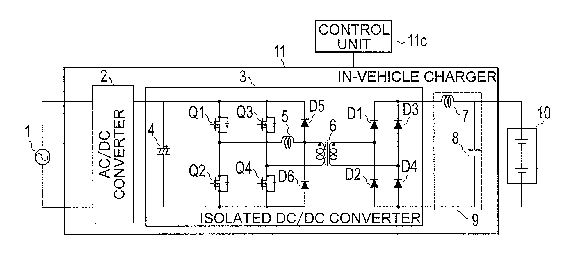
[0061]FIG. 1 is a schematic configuration diagram of an entire in-vehicle charger according to a first embodiment of the present invention. As illustrated in FIG. 1, on the input side of an in-vehicle charger 11, an AC power supply 1 (hereinafter simply referred to as “AC power supply 1”) serving as an external power supply (AC input power supply) is connected. Further, on the output side of the in-vehicle charger 11, a battery 10 having a high voltage (hereinafter referred to as “high-voltage battery 10”) serving as a load is connected. The high-voltage battery 10 supplies stored power to an electric motor for driving a vehicle.

[0062]The in-vehicle charger 11 includes an AC / DC converter 2 configured to convert an AC voltage into a DC voltage, and an isolated DC / DC converter 3 configured to step up the DC voltage generated by the AC / DC converter 2 and apply the stepped-up DC voltage to the high-voltage battery 10, to thereby supply power to the high-voltage battery 10. Further, a ca...

second embodiment

[0117]A description is now given of an in-vehicle charger according to a second embodiment of the present invention. While the switching system is described as the hard switching in the first embodiment, the configuration of the present invention can provide a greater effect by the control unit 11c carrying out phase shift control, which is the soft switching. A description is now given of this point. FIG. 13 is a schematic configuration diagram for illustrating the in-vehicle charger 11, which is the circuit portion of the in-vehicle charger according to the second embodiment.

[0118]The circuit configuration is almost the same as that of the first embodiment, but each of capacitors for resonance (hereinafter referred to as “resonance capacitors”) C1 to C4 is connected between the drain and the source of one of the semiconductor switching elements Q1 to Q4.

[0119]Each of the resonance capacitors C1 to C4 is an external capacitor, but is not limited to the external capacitor, and may b...

third embodiment

[0138]A description is now given of an in-vehicle charger according to a third embodiment of the present invention. The in-vehicle charger 11 described in the second embodiment suppresses a step-up rate of the voltage of the capacitor 4 output by the AC / DC converter 2, the control unit 11c drives the isolated DC / DC converter through the phase shift control, and the semiconductor switching elements Q3 and Q4 are caused to start to be turned on / off earlier than the semiconductor switching elements Q1 and Q2 (refer to FIG. 14), thereby increasing the possibility of establishing the ZVS. However, on the other hand, the primary-side current of the isolated transformer 6 and the surge current of the resonance reactor 5 flow through the resonance reactor 5, and the current flowing through the resonance reactor 5 is thus large (refer to FIG. 14). Further, the same current also flows through the semiconductor switching elements Q1 and Q2 during every other half cycle (refer to FIG. 15 to FIG...


PUM


Abstract

An isolated DC / DC converter (3) includes a full-bridge type switching circuit. A primary winding of a transformer (6) and a resonance reactor (5) are connected in series to each other. Another end of each of the primary winding and the resonance reactor (5) is connected to one of middle points between switching elements. First and second surge suppression diodes (D5 and D6) are provided to a node between the resonance reactor (5) and the primary winding of the transformer (6) and between a positive side and a negative side of a capacitor (4). This configuration suppresses a surge voltage applied to the transformer by releasing surge energy of the resonance reactor (5) caused by a recovery of rectifying diodes (D1 to D4) on a secondary side of the transformer (6) via the surge suppression diodes (D5 and D6).

Description

TECHNICAL FIELD[0001]The present invention relates to an in-vehicle charger configured to charge a battery for supplying power to an electric motor for an electric vehicle such as an electric car (EV) or a plug-in hybrid electric car (PHEV).BACKGROUND ART[0002]As types of electric vehicles, there are known a vehicle including only an electric motor as a drive source, and a hybrid vehicle including an electric motor and an engine as drive sources. The electric vehicle of any of those types includes a battery serving as an electricity storage device configured to supply power to the electric motor, and the battery is required to be charged from the outside when the remaining capacity of the battery is low. Further, in the hybrid vehicle including the electric motor and the engine as the drive sources, in normal, the battery is charged by driving the engine. Note that, the battery is sometimes charged by supplying power from an external power supply without driving the engine.[0003]In ...

Claims


Application Information

Patent Timeline
Patent Type & Authority Applications(United States)
IPC IPC(8): B60L11/18H02M3/335
CPCB60L11/1811B60L2210/30B60L2210/10H02M3/33546H02M3/3353H02M3/3376B60L2240/525Y02T10/92Y02T10/7072Y02T90/14B60L53/22Y02T10/72Y02T10/70H02M1/0058H02M7/53878H02M3/33573H02M3/01B60L53/20Y02T90/12
Inventor KAWAMURA, MAOMATSUDA, YOHEI
Owner MITSUBISHI ELECTRIC CORP
Why Eureka
Try Eureka