
Wastewater treatment system

a technology of nitrification and treatment system, applied in the direction of biological water/sewage treatment, sustainable biological treatment, water/sewage treatment by degassing, etc., can solve the problems of complex de-nitrification process, aqueous environment, and harmful effect of nitrate generated in the nitrification step, so as to reduce the complexity and operating cost, eliminate the complex and costly nitrification and de-nitrification steps, and reduce the size and cost

Inactive Publication Date: 2017-02-23
BLUMETRIC ENVIRONMENTAL
View PDF0 Cites 16 Cited by
  • Summary
  • Abstract
  • Description
  • Claims
  • Application Information

AI Technical Summary

Benefits of technology

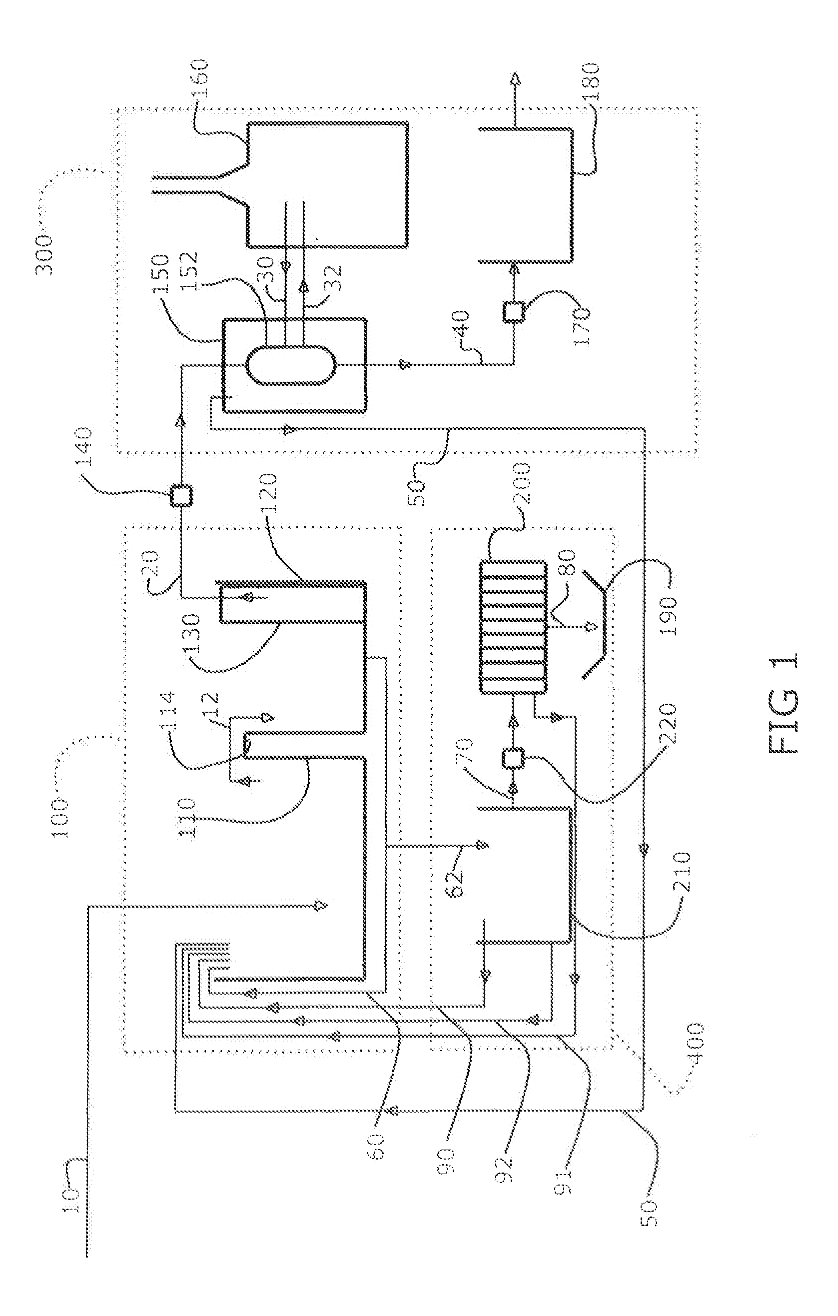
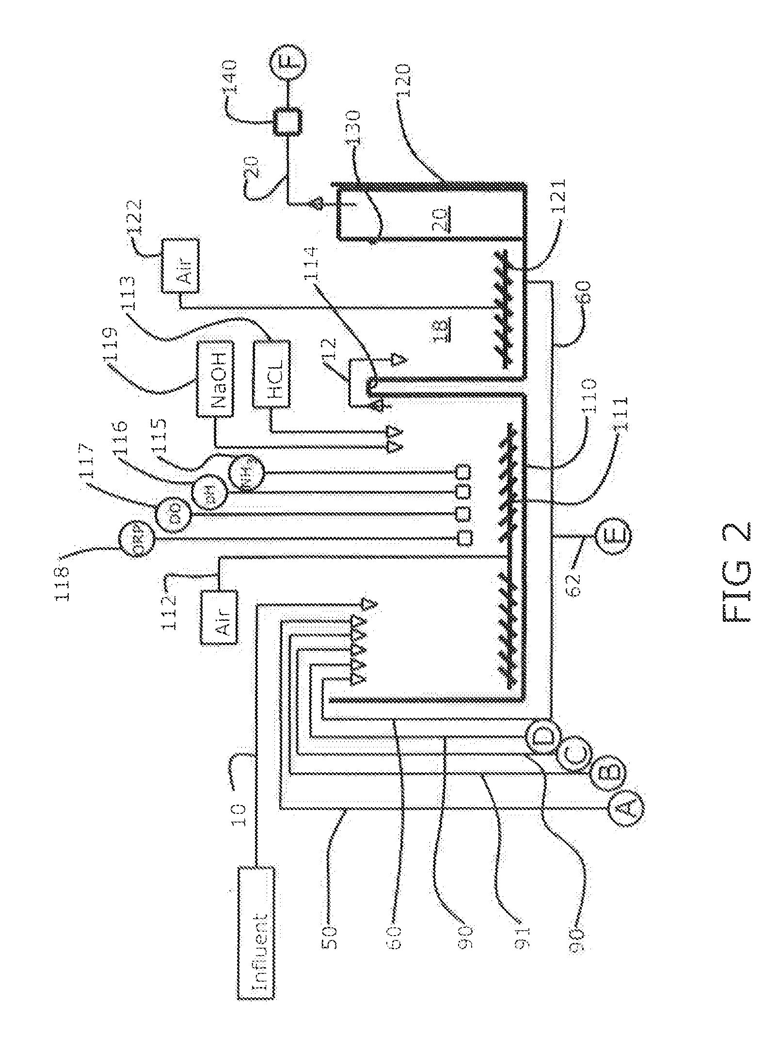
The invention provides a wastewater treatment process that eliminates the need for nitrification and de-nitrification steps, resulting in reduced complexity and lower costs compared to traditional systems. The process uses a reactor to remove carbon and nitrogen oxides from wastewater with the aid of aerobic microorganisms. The ammonia is selectively removed from the reaction mixture using an ion-selective resin, reducing the size and cost associated with traditional nitrification and de-nitrification processes. The use of an ammonia re-claimer allows for the capture and recycling of contaminants. The system also includes a variable depth reactor and membrane bioreactor for efficient treatment of wastewater with high quality effluent at a low cost.

Problems solved by technology

The nitrate generated in the nitrification step has been found to have a detrimental impact, in particular on aqueous environments.
However, the de-nitrification process is complicated and requires the addition of a carbon based food source to satisfy the metabolic needs of the anoxic microorganisms as they break the nitrate.
Consequently, the nitrification and de-nitrification process adds significantly to the complexity and cost of the overall system.

Method used


Image

  • Wastewater treatment system
  • Wastewater treatment system
  • Wastewater treatment system

Examples


example

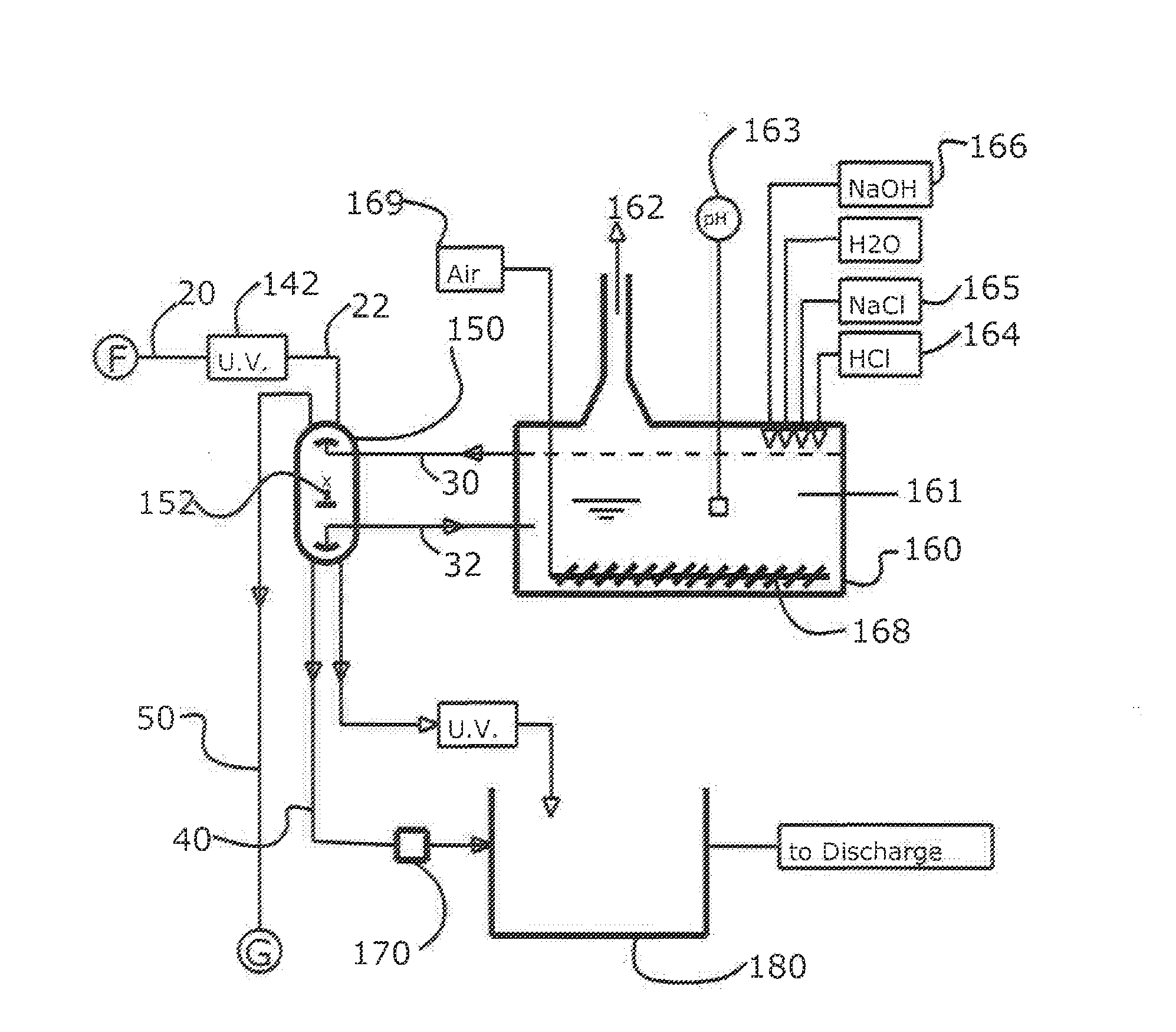
[0049]A pilot test program was developed to determine the best manner to reduce the oxygen demand created by wastewater generated from an existing wastewater management facility (Facility 1). Initial evaluation of the varied wastewater streams showed that certain streams carried the highest potential for effective reduction of both ammonia and BOD. An exemplary pilot system in accordance with the invention was constructed and tests were run to assess the efficacy of ion exchange resin at removing ammonia from blended landfill leachate water, as well as pre-treated process water. Following ammonia removal by ion exchange, BOD removal was tested using a 3:1 ratio of activated sludge from the Middletown Municipal Wastewater Treatment Plant (Middletown WWTP) to sample. BOD removal was tested on a blended landfill leachate stream, and a pretreated wastewater stream over varying time intervals, following contact with the ion exchange bed, as well as a sample of wastewater from a second fa...


PUM

PropertyMeasurementUnit
concentrationaaaaaaaaaa
diameteraaaaaaaaaa
diameteraaaaaaaaaa

Abstract

In a process for the treatment of wastewater containing carbonaceous and nitrogenous contaminants, wastewater is mixed with aerobic microorganisms capable of converting carbonaceous biological oxygen demand (CBOD) into carbon dioxide, water, and biological cell mass. Oxygen is supplied to the reaction mixture for supporting reduction of the CBOD by the aerobic microorganisms in the reaction mixture. To substantially prevent nitrification of the nitrogenous contaminants in the reaction mixture and avoid the cost of downstream denitrification, the hydraulic residence time of the nitrogenous contaminants in the reaction mixture is controlled by removing partially treated water with dissolved ammonia from the reaction mixture, while retaining the biological cell mass in the reaction mixture. This separates the nitrogen load from the carbon load and enables independent treatment of these contaminants. The ammonia is scrubbed from the partially treated water to create fully treated water which is disposed or returned to the reaction mixture.

Description

RELATED APPLICATIONS[0001]This application claims priority from Provisional U.S. Patent Application No. 62 / 207,754, which was filed on Aug. 20, 2015, and is incorporated herein by reference.FIELD OF THE INVENTION[0002]The present invention relates generally to wastewater treatment and in particular to residential, industrial and municipal waste water treatment processes and systems.BACKGROUND[0003]Most wastewater contains organic contaminants that fall into two groups; carbonaceous, which is derived from sugars, starches and other carbohydrates, and nitrogenous, which comes from the degradation of more complex compounds, such as proteins and amino acids, into ammonia. Most conventional treatment systems address these contaminants separately by using different species of aerobic microorganisms which can use the contaminants as food source. Generally, naturally occurring microorganisms are used and maintained in an environment that keeps them in intimate contact with the food source a...

Claims


Application Information

Patent Timeline
Patent Type & Authority Applications(United States)
IPC IPC(8): C02F3/26C02F1/42C02F1/66C02F3/00C02F3/10C02F1/20
CPCC02F3/26C02F3/102C02F1/20C02F1/66C02F2209/005C02F1/42C02F2209/04C02F2209/22C02F2209/40C02F3/006C02F3/1273C02F3/20C02F2209/001C02F2209/06C02F2209/08C02F2209/14C02F2209/44Y02W10/10
Inventor SCROGGINS, DANNY LEE
Owner BLUMETRIC ENVIRONMENTAL
Learn More