Optical filter

a technology of optical filters and filters, applied in the field of optical filters, can solve the problems of insufficient ultraviolet absorbing performance of optical filters, inability to achieve a maximum absorption wavelength in an appropriate wavelength band, etc., to achieve excellent absorption properties, reduce the size of optical filters, and high shielding performance

Active Publication Date: 2017-06-29
ASAHI GLASS CO LTD
View PDF2 Cites 13 Cited by
  • Summary
  • Abstract
  • Description
  • Claims
  • Application Information

AI Technical Summary

Benefits of technology

[0026]In the optical filter of the present invention, the near infrared absorbing dye (A) and the near ultraviolet absorbing dye (U) used have such properties that the inclination in the vicinity of a visible region boundary in each of their spectral transmittance curves is steep, and they have high shielding performance in the absorption wavelength region. Accordin

Problems solved by technology

However, with such compounds, the optical filter does not have a sufficient near ultraviolet absorbing performance and does not have a maximum absorption wavelength in an appropriate wavelength band.
However, if the amount of addition of the compound is increased or the thickness of the transparent resin is increased so as to satisfy the above optical properties, properties of the resin may be impaired.
For example, in a case where a dielectric multilayer film as a light reflecting layer is formed on a glass substrate by deposition, a stress may occur between layers by the heating/cooling procedure in the evaporation step, and cracking or breakage may occur, and

Method used

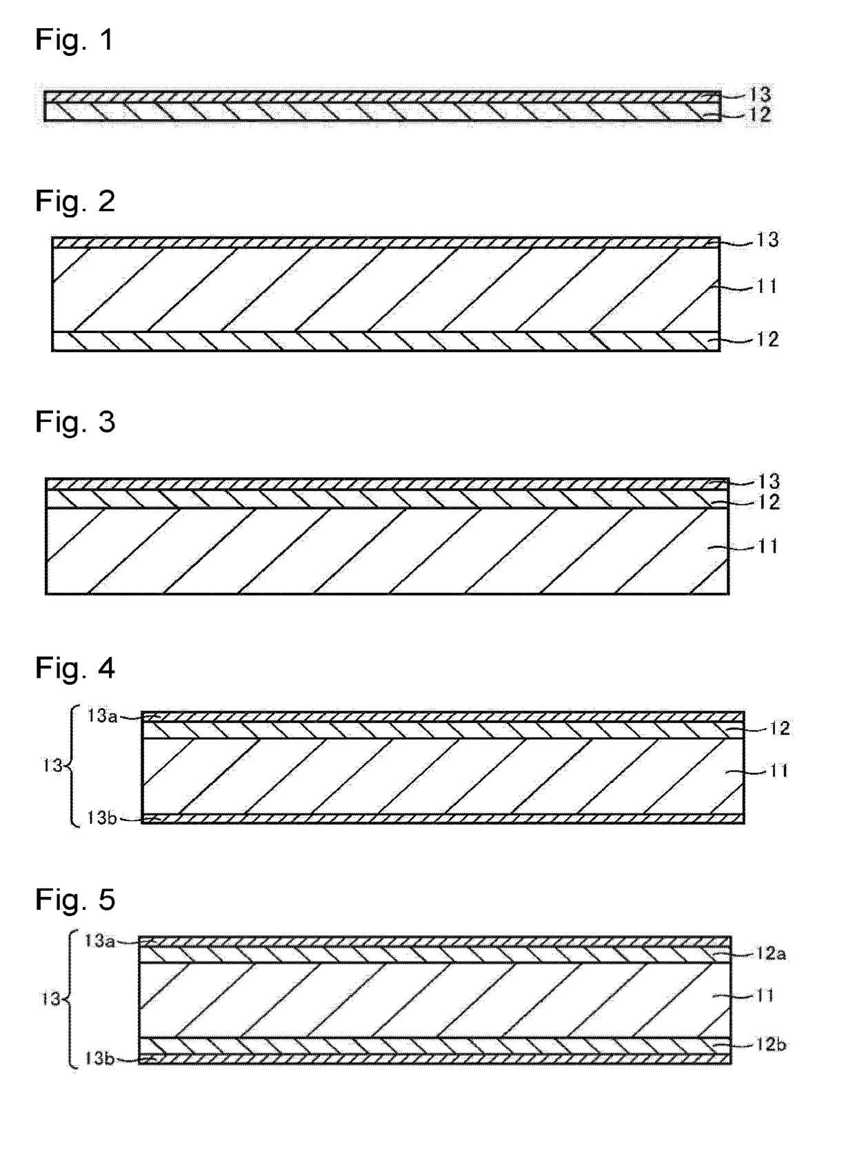

Image

  • Optical filter
  • Optical filter
  • Optical filter

Examples


example 1

[Evaluation]

[0154]The transmittance in each Ex. was calculated by measuring the spectral transmittance curve at a wavelength of from 300 to 800 nm using an ultraviolet visible spectrophotometer (manufactured by Hitachi High-Technologies Corporation, U-3300). Dichloromethane was used as a solvent, and the maximum absorption wavelength (λmax [unit: nm]) and the molar absorptivity (unit: [L / mol·cm)]) at that wavelength are shown. In the following Ex. also, the spectral transmittance curve was measured by using U-3300 manufactured by Hitachi High-Technologies Corporation.

TABLE 2Evaluation Ex.λmaxε (molar absorptivity)No.Dye[nm][L / (mol · cm)]Eval. Ex. 1(U-2)39685,628Eval. Ex. 2(U-9)37968,968Eval. Ex. 3(U-11)39056,607Eval. Ex. 4(B-2)37728,087Eval. Ex. 5(B-1)33920,168Eval. Ex. 6(B-3)33915,555

example 2

[0155]The dye (U) illustrated in Table, the dye (A1-1) and fluorene ring-containing polyester OKP-850 were dissolved in a cyclohexanone solution, the solution was applied to a glass substrate and dried to prepare a dye-containing transparent resin body, and the transmission spectrum at a wavelength of from 300 to 800 nm was measured. The results are shown in Tables 3-1 and 3-2. Ex. 2-1 to 2-10 are Examples of the present invention, and Ex. 2-11 to 2-16 are Comparative Examples.

[0156]The dye concentration is represented by part by mass (PHR) of the dye in 100 parts by mass of the transparent resin (the same applies hereinafter). Further, in Tables, the IR absorption width is a band width within which the transmittance is at most 1% in the infrared region, the IR maximum absorption wavelength is the maximum absorption wavelength in the infrared region, and the UV maximum absorption wavelength is the maximum absorption wavelength in the ultraviolet region.

TABLE 3-1Ex. No.Ex. 2-1Ex. 2-2...

example 3

[0157]The dye (U) illustrated in Table, the dye (A1-1) and fluorene ring-containing polyester B-OKP2 were dissolved in a cyclohexanone solution, the solution was applied to a glass substrate and dried to prepare a dye-containing transparent resin body, and the transmission spectrum at a wavelength of from 300 to 800 nm was measured. The results are shown in Tables 4-1 and 4-2. Ex. 3-1 to 3-7 are Examples of the present invention, and Ex. 3-8 to 3-13 are Comparative Examples.

[0158]As shown in Tables, in Ex. 3-1 to 3-7, the difference (λ(UV70)−λ(UV15)) between the wavelength λ(UV15) at which the transmittance is 15% and the wavelength λ(UV70) at which the transmittance is 70% within a wavelength range of from 380 to 430 nm, is at most 30 nm, and the wavelength λ(UV50) at which the transmittance is 50% is within a wavelength range of from 400 to 440 nm, and sufficient shielding performance is obtained within a desired wavelength band even with a film thickness of about 1 μm. In such a ...


PUM


Abstract

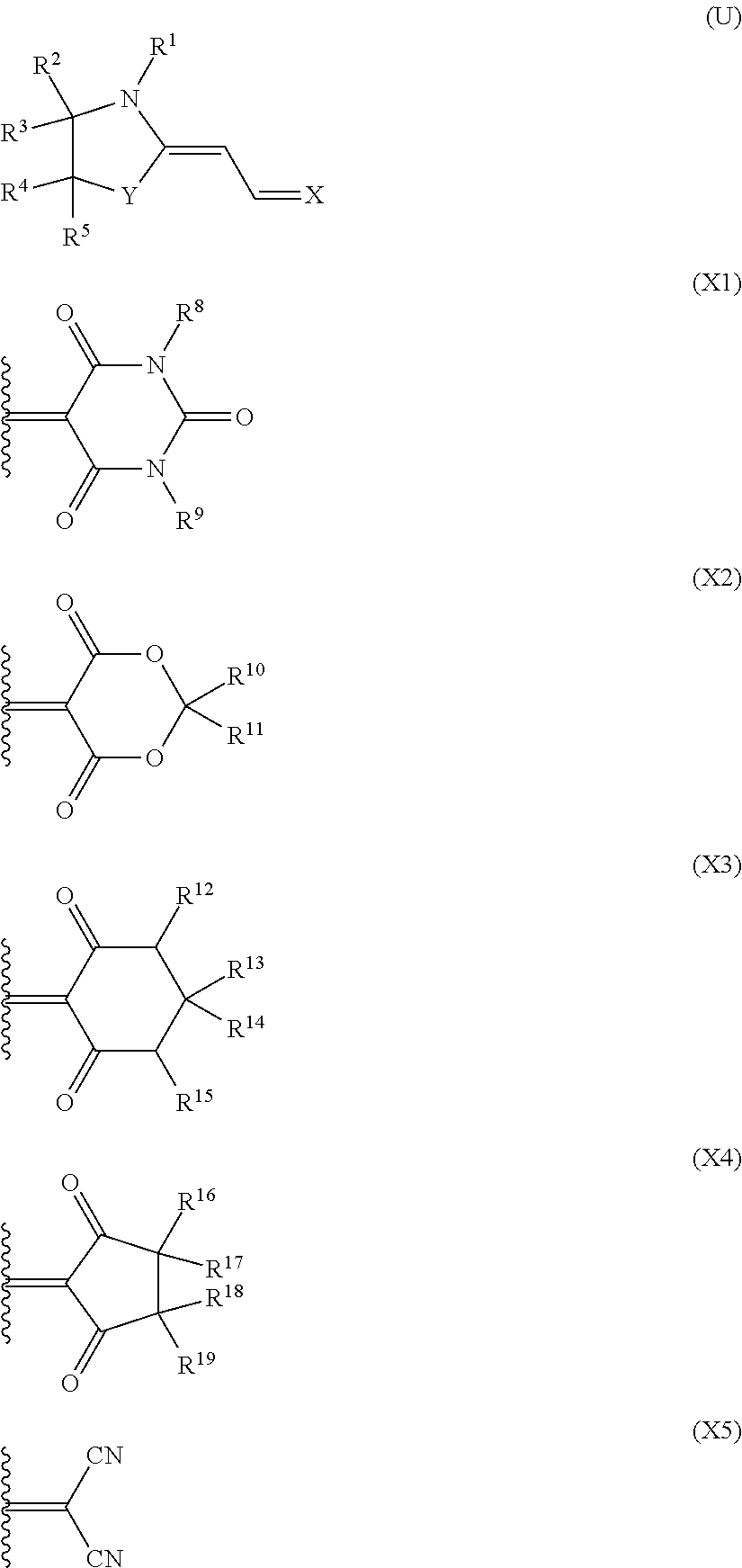
To provide an optical filter having shielding effects against near ultraviolet rays and near infrared rays. An optical filter comprising a transparent resin body having a single layer or multilayer structure, and containing a near ultraviolet absorbing dye (U) which is a compound represented by the following formula (U) and which has an absorption maximum at a wavelength of from 370 to 425 nm and has a molar absorptivity at the maximum absorption wavelength of at least 50,000 [L/(mol·cm)], and a near infrared absorbing dye (A) which has an absorption maximum at a wavelength of from 600 to 800 nm:
In the formula (U), Y is an oxygen atom, a methylene group or a dimethylene group, R1 is a monovalent hydrocarbon group which may have a substituent, or the like, R2 to R5 are a hydrogen atom, an alkyl group, an alkoxy group or the like, and X is a bivalent group represented by any one of the formulae (X1) to (X5) or the like.

Description

TECHNICAL FIELD[0001]The present invention relates to an optical filter having shielding effects against near ultraviolet rays and near infrared rays.BACKGROUND ART[0002]In recent years, for various applications, an optical filter which sufficiently transmits light in the visible wavelength region and which blocks light in the near ultraviolet wavelength region and the near infrared wavelength region has been used.[0003]Hereinafter, “visible wavelength region”, “(near) ultraviolet wavelength region” and “(near) infrared wavelength region” will be referred to as “visible region”, “(near) ultraviolet region” and “(near) infrared region”, respectively, and “light in the visible wavelength region”, “light in the (near) ultraviolet wavelength region” and “light in the (near) infrared wavelength region” will be referred to as “visible light”, “(near) ultraviolet light” and “(near) infrared light”, respectively.[0004]For example, in imaging devices using a solid-state imaging element (e.g....

Claims


Application Information

Patent Timeline
IPC IPC(8): G02B5/20C09B57/00C09B23/10G02B5/22G02B5/08
CPCG02B5/208G02B5/223C09B57/007C09B23/105G02B5/0808
Inventor SHIONO, KAZUHIKOYOSHIOKA, ASANASUZUKI, SHOKOHOTAKA, HIROKI
Owner ASAHI GLASS CO LTD
Why Eureka
Try Eureka