Electrode apparatus

a technology of electrodes and electrodes, which is applied in the field of electrode apparatuses, can solve the problems of difficult identification of which part of the electrical path between the electrodes is causing the high impedance, dangerous concentration of current over a small skin area, and a large amount of current, so as to improve the characterisation of the impedance within the head and accurate estimation of the dosage

Inactive Publication Date: 2018-12-06
CERESTIM
View PDF0 Cites 9 Cited by
  • Summary
  • Abstract
  • Description
  • Claims
  • Application Information

AI Technical Summary

Benefits of technology

[0127]Typically the pairing electrodes comprise one or more electrodes of the second electrode module. This can help to ensure that the electrical signals applied between the electrodes of the (first) electrode module and the pairing electrodes flow through the head (and not just the electrolyte application region).
[0128]As mentioned above, it may be that individual electrodes, or sub-sets of electrodes, of the (first) or each electrode module are physically and / or electrically segregated from other individual electrodes or sub-sets of electrodes of that module (e.g. by electrically insulating walls extending between them, which typically form a seal with the skin interface). Again, this helps to ensure that electrical signals applied between the electrodes of the (first) electrode module flow through the head (and not just between electrodes through the electrolyte application region), which helps to better characterise the impedance within the head, thereby allowing more accurate estimate of the dosage of electrical stimulation applied to the target treatment region. It may be that the walls are hexagonal in shape (e.g. when viewed in plan along a line of shortest distance between the first and second ends of the electrode module). It may be that the said walls define said localised sub-regions of the electrolyte application region.

Problems solved by technology

The invasive technologies rank high in spatial resolution but require expensive and risky neurosurgery and are therefore not used in less extreme cases.
However, in the event of a high impedance value being detected between the electrodes, it is difficult to identify which part of the electrical path between the electrodes is causing the high impedance (e.g. (a) due to the electrolyte, (b) due to the skin-scalp interface, (c) due to the skin, skull, intermediate layers or cortex, (d) due to the direct shunt between the electrodes over the skin).
In addition, local changes in the impedance between the electrodes and the skin, which could lead to dangerous concentration of current over a small skin area without significant change in the total impedance, cannot be resolved.
Each iteration may take several minutes, and it is difficult to maintain the right level of electrical contact between the electrode and the skin during a stimulation session.
It is also difficult to determine the electrical stimulation dosage impinging on a target treatment region internal to the brain.
That is, it is difficult to estimate the exact electrical flux which impinges on the neurons in the target treatment region of the brain.
Indeed it is difficult to control the penetration of the applied electrical field to the brain through the skin and other upper layers between the electrode and the brain.
Having inaccurate control of dosing implies a risk of accidental over-dosing of stimulation; under-dosing and therefore inadequate stimulation; and simply uncontrolled dosing.
This lack of control of effective dose thus presents a significant problem.
Another issue with the TES set-ups shown in FIGS. 1A, 1B is that the only way of identifying discomfort of a patient is by communication with the subject.
It also means that side effects may only be addressed once the subject is aware of them.
An EEG signal is very small, typically 10 to 100 micro volts measured at the scalp, and thus subject to pick-up of electrical noise and other artefacts.
Therefore positioning of an entire EEG montage, which may contain as many as 128 electrodes, and establishment and checking of conductivity is very time consuming.
In addition, it is time consuming to verify and then maintain the correct impedance between the electrodes and the scalp during the measurement process.
In both existing approaches to TES shown in FIGS. 1A, 1B and the existing approach to EEG shown in FIG. 3, the electrolyte between the electrodes and the skin interface is messy, which leads to inconvenience (and low usability) for the clinician and subject.
Saline tends to run down the patients head and neck and electro-gel and electro-paste tend to get caught in the subject's hair.
Furthermore, the electrolyte between the electrode and the skin interface is prone to drying out (e.g. low viscosity electrolyte, like saline, may evaporate or flow away from the region between the electrode and the skin interface under gravity), thereby leaving insufficient electrolyte between the electrode and the skin interface.
This leads to poor electrical conductivity between electrode and skin interface which in the case of EEG leads to poor signal to noise ratio and, in the case of TES, leads to the risk of increased skin sensitivity and current density applied to the scalp by the electrodes.
Relying on the clinician to be vigilant can be risky as deviations may be missed and the subject exposed to overdoses or unwanted side effects.

Method used


Image

  • Electrode apparatus
  • Electrode apparatus
  • Electrode apparatus

Examples


Embodiment Construction

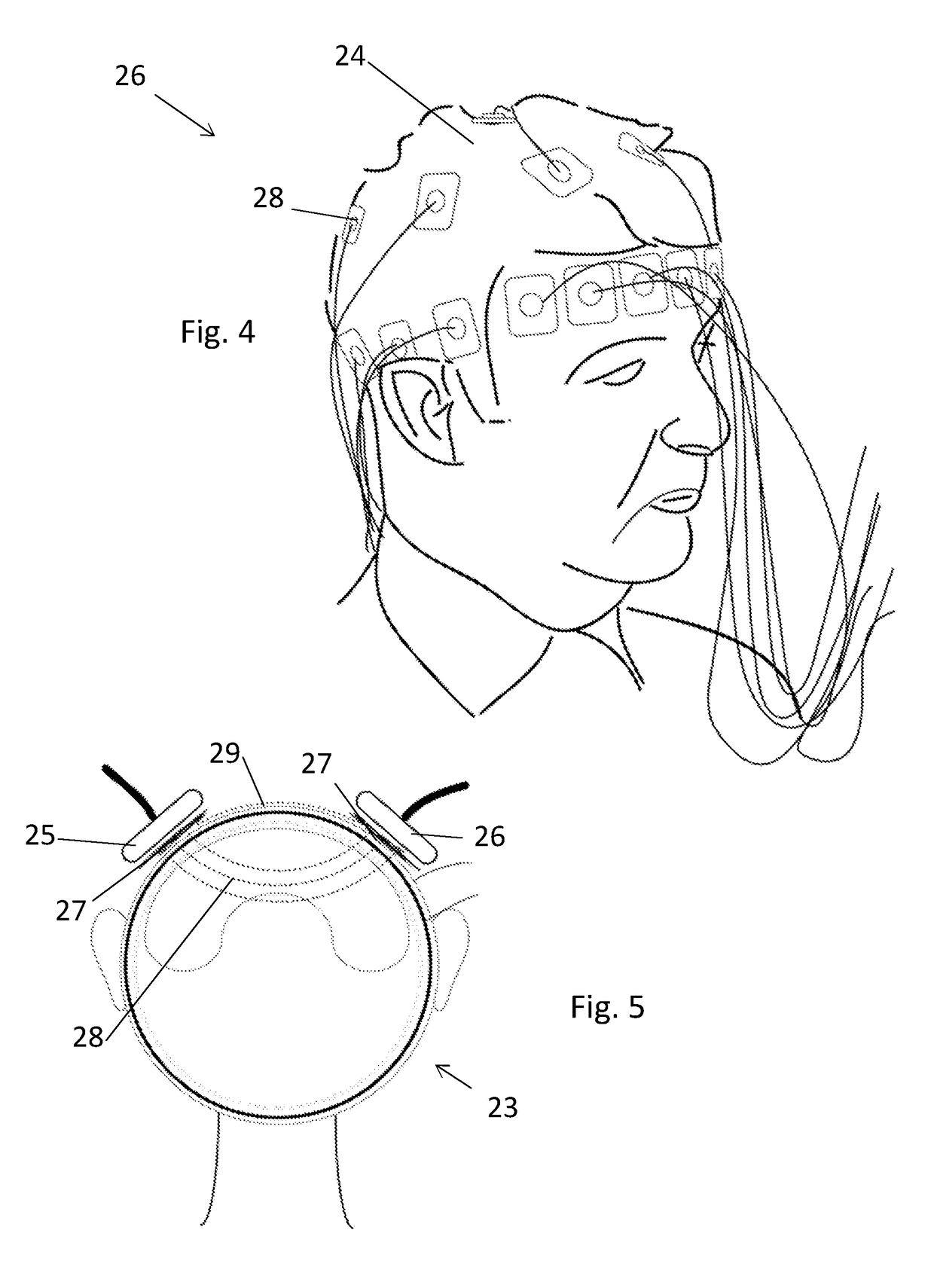
[0652]FIG. 4 illustrates an application of electrical impedance tomography to determine an image 23 of the head 24 of a subject 26 using a plurality of point electrodes 28 attached to the head 24. Typically, a plurality of 2D images are determined from measurements made using the electrodes 28, and the 2D images are combined for form a ‘real’ 3D geometric brain / head model of the impedance of the head, where the greyscale value represents the reconstructed impedance value from the measured data. FIG. 5 illustrates a simplified conceptual mathematical model 23 of the impedance of the human head for transcranial electrical stimulation, the model 23 comprising several tissue / impedance layers inside the head, two monolithic electrodes 25, 26, electrolyte 27 and electrical current flow 28, 29 through the head and shunted across the scalp.

[0653]FIG. 6A illustrates a transcranial electrical stimulation session of a human subject 40, typically under the control of a clinician 42 (although it...


PUM

PropertyMeasurementUnit
electrical currentsaaaaaaaaaa
impedanceaaaaaaaaaa
wavelengthaaaaaaaaaa

Abstract

The invention provides electrode apparatus for non-invasively applying electrical stimulation to a body portion of a human subject by way of a skin interface, the electrode apparatus comprising: an electrode module having: an end for defining an electrolyte application region between the electrode module and the skin interface; and a plurality of electrodes which are electrically couplable or electrically coupled to the skin interface by way of an electrolyte in the said electrolyte application region, the electrodes being spaced apart from each other; and a controller in communication with the electrodes, the controller being configured to individually adjust electrical signals across or between each of the said electrodes and each of one or more pairing electrodes.

Description

FIELD OF THE INVENTION[0001]The invention relates to electrode apparatus, methods of non-invasively applying electrical stimulation to a body portion of a human subject by way of a skin interface; methods of non-invasively applying electrical stimulation to, or detecting electrical signals from, a body portion of a human subject by way of a skin interface; methods of non-invasively applying a dosage of electrical stimulation to a body portion of a human subject by way of a skin interface; data processing apparatus; methods of estimating a dosage of electrical stimulation impinging on a target treatment region internal to a human body portion; electrode modules for non-invasively applying electrical stimulation to a body portion; and electricity for treatment of a neurological or psychiatric disorder and / or to influence mood and / or cognition.BACKGROUND TO THE INVENTION[0002]Neuromodulation is widely used to study and treat the brain (as well as other parts of the body), presenting an...

Claims


Application Information

Patent Timeline
Patent Type & Authority Applications(United States)
IPC IPC(8): A61N1/04A61B5/053A61B5/00A61N1/36A61B5/107G01N27/02
CPCA61N1/0496A61B5/0531A61B5/6843A61N1/0456A61N1/0476A61N1/36031A61B5/0536A61B5/107G01N27/026A61B2018/1472A61B2562/0217A61B2562/14A61N1/36025A61N1/36034A61B5/4064A61B5/0042A61B5/02405A61B5/1101A61B5/165A61B5/445A61B5/291A61B5/053A61N1/04A61N1/18
Inventor AMBROSE, ALAN
Owner CERESTIM
Why Eureka
Try Eureka