Evaporative fuel vapor emission control systems

a technology of emission control system and evaporative fuel, which is applied in the direction of machines/engines, separation processes, mechanical equipment, etc., can solve the problems of affecting tailpipe emissions, one size does not fit all, and complicating management, etc., and achieves low purge volume, low dbl, and low purge

Active Publication Date: 2018-12-20
INGEVITY SOUTH CAROLINA
View PDF0 Cites 16 Cited by
  • Summary
  • Abstract
  • Description
  • Claims
  • Application Information

AI Technical Summary

Benefits of technology

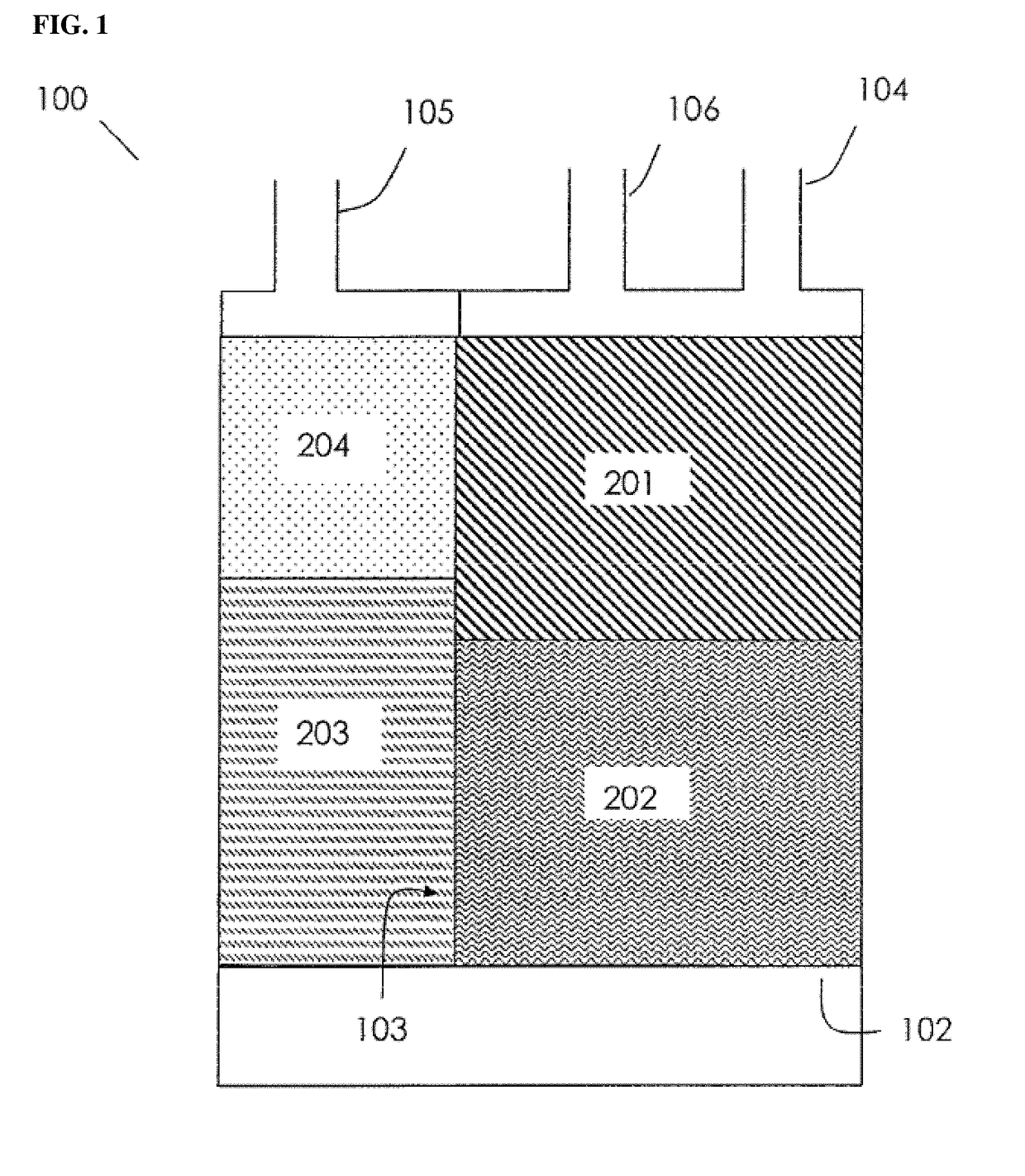
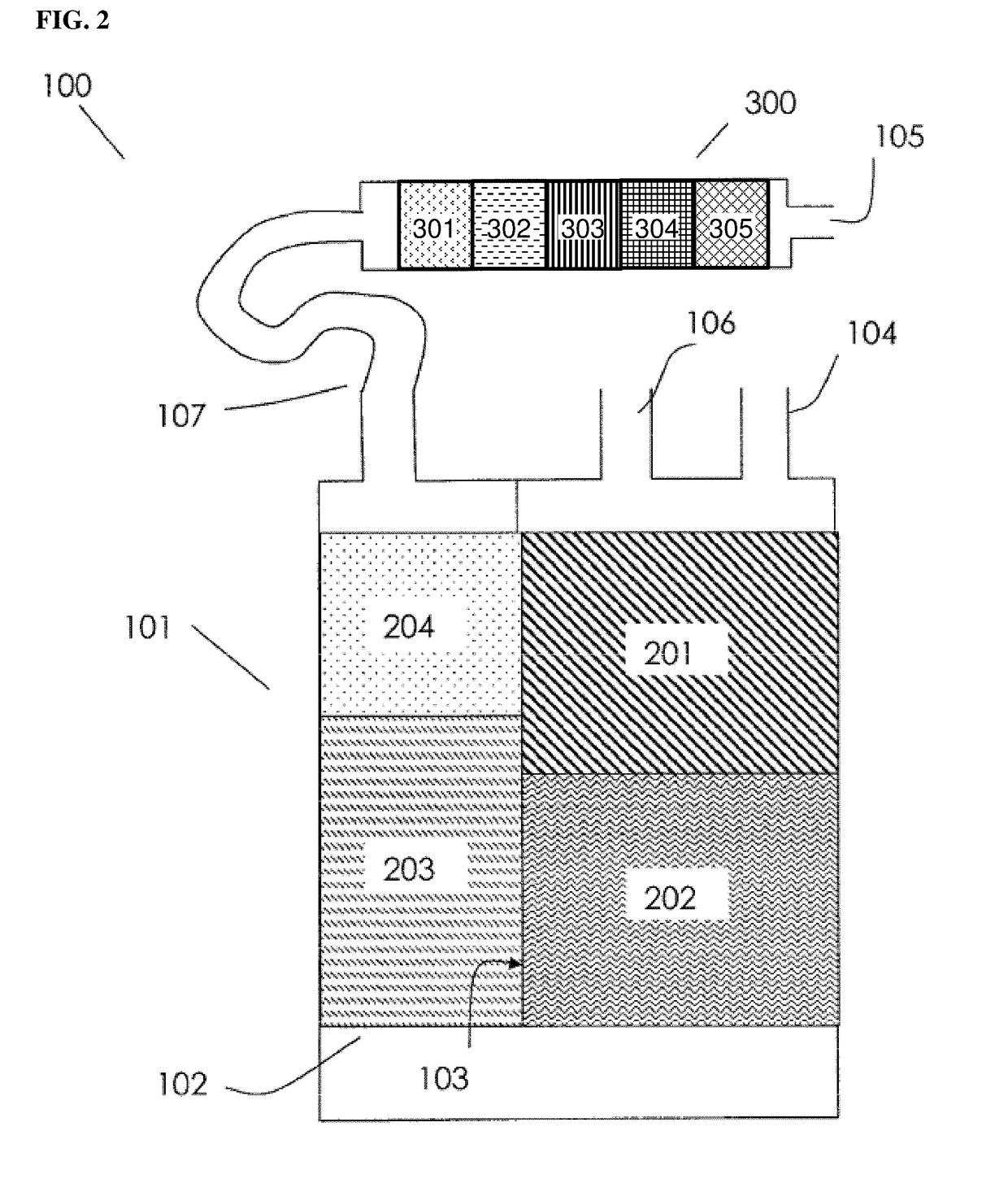
[0019]Presently described are evaporative emission control canister systems with surprising and unexpected characteristics, including two-day diurnal breathing loss (DBL) emissions of less than about 50 mg or less than about 20 mg, including in instances with relatively low volumes of purge (e.g., less about 175 BV or less than 100 BV). It was surprisingly and unexpectedly discovered that low purge and low DBL evaporative emission control canister systems are possible with particulate adsorbent volum...

Problems solved by technology

Evaporation of gasoline fuel from motor vehicle fuel systems is a major source of hydrocarbon air pollution.
Certainly, “one size does not fit all” for canister system design and its adsorbent fills.
This approach, however, has the drawback of complicating management of the fuel/air mixture to the engine during the purge step and tends to adversely affect tailpipe emissions.
For certain high performance and high fuel efficiency engine designs, including turbo-charged, gasoline direct injection, and hybrid electric vehicles, such high purge is not available or might greatly affect engine performance.
One drawback of such approach is that the relatively low cross-sectional area imparts an excessive flow restriction to the canister for solid-shaped conventional particulate adsorbents of 1-3 mm diameter, except for the shortest bed length which then otherwise compromises the effectiveness of this vent-side chamber for DBL emission control.
Therefore, though potentially effective for reducing bleed emissions of the system, the excessive flow restriction is not accommodated by conventional particulate adsorbent.
However, this approach increases the complexity of control system management and poses some safety concerns.
While such an adsorbent structure provides the desired adsorptive properties with low flow restriction, these engineered parts are costly to make, requiring special skill and equipment to manufacture, and the immediate initial customer, the designer of canister systems, is limited to only those size honeycomb parts that are normally available for system design, testing and certification.
While these pellets may have useful adsorptive properties for bleed emission control and, as a particulate material, allow great flexibility for the adsorbent chamber dimensions into which these pellets are filled, these pellets have high flow restriction properties relative t...

Method used


Image

  • Evaporative fuel vapor emission control systems
  • Evaporative fuel vapor emission control systems
  • Evaporative fuel vapor emission control systems

Examples


examples

[0216]Determination of Apparent Density

[0217]The standard method ASTM D 2854-09(2014) (hereinafter “the Standard Method”) may be used to determine the apparent density of particulate adsorbents, taking into account the prescribed minimum ratio of 10 for the measuring cylinder diameter to mean particle diameter of the particulate material, with mean particle diameter measured according to the prescribed standard screening method.

[0218]Determination of Macroscopic Pore Volume

[0219]Macroscopic pore volume is measured by mercury intrusion porosimetry method ISO 15901-1:2016. The equipment used for the examples was a Micromeritics Autopore V (Norcross, Ga.). Samples used were around 0.4 g in size and pre-treated for at least 1 hour in an oven at 105° C. The surface tension of mercury and contact angle used for the Washburn equation were 485 dynes / cm and 130°, respectively. Macropores as referred to herein, are those that have a diameter of from about 100 nm to about 100,000 nm.

[0220]Dete...


PUM

PropertyMeasurementUnit
Lengthaaaaaaaaaa
Fractionaaaaaaaaaa
Fractionaaaaaaaaaa

Abstract

The present disclosure describes an evaporative emission control canister system that includes: one or more canisters comprising at least one vent-side particulate adsorbent volume comprising a particulate adsorbent having microscopic pores with a diameter of less than about 100 nm; macroscopic pores having a diameter of about 100-100,000 nm; and a ratio of a volume of the macroscopic pores to a volume of the microscopic pores that is greater than about 150%, and having a retentivity of about 1.0 g/dL or less. The system may further include a high butane working capacity adsorbent. The disclosure also describes a method for reducing emissions in an evaporative emission control system.

Description

CROSS REFERENCE TO RELATED APPLICATIONS[0001]This application claims priority to U.S. Provisional Patent Application 62 / 521,912 filed 19 Jun. 2017, and U.S. Provisional Patent Application 62 / 685,174 filed 14 Jun. 2018, the contents of which are incorporated herein by reference in their entirety for all purposes.BACKGROUND1. Field of the Discovery[0002]The present disclosure generally relates to a system comprising particulate adsorbent material and methods of using the same. More particularly, the present disclosure relates to a system comprising a low retentivity particulate adsorbent material and methods of using the same in evaporative fuel vapor emission control systems.2. Background Information[0003]Evaporation of gasoline fuel from motor vehicle fuel systems is a major source of hydrocarbon air pollution. Such emissions can be controlled by the canister systems that employ activated carbon to adsorb the fuel vapor generated by the fuel systems. Under certain modes of engine op...

Claims


Application Information

Patent Timeline
IPC IPC(8): F02M25/08B01D53/04
CPCF02M25/0854B01D53/0415B01D53/0438B01D2253/102B01D2253/3425B01D2257/708B01D2259/4516B01D53/0407F02M25/089B01D2253/104B01D2253/106B01D2253/108B01D2253/11B01D2253/1124B01D2253/308B01D2253/311B01D2253/34B01D2257/7022B01D2259/40086B01D2259/41B01D2259/4145B01D53/02B01D2253/202B01D2253/116
Inventor BYRNE, TIMOTHY M.HILTZIK, LAURENCE H.LEON GARCIA, MARTATHOMSON, CAMERON I.
Owner INGEVITY SOUTH CAROLINA
Why Eureka
Try Eureka