Catalytic reactor configuration, preparation and method of direct synthesis of ethylene through oxygen-free catalysis of methane

Active Publication Date: 2019-05-16
DALIAN INST OF CHEM PHYSICS CHINESE ACAD OF SCI
View PDF1 Cites 25 Cited by
  • Summary
  • Abstract
  • Description
  • Claims
  • Application Information

AI Technical Summary

Benefits of technology

[0016]The present invention to solve the technical problem is: to overcome defects of the prior art and to provide a catalytic reactor configuration, preparation and a method of direct synthesis of ethylene through oxygen-free catalysis of methane. The present invention has the characteristics of long life of catal

Problems solved by technology

%, it will be difficult

Method used


Image

  • Catalytic reactor configuration, preparation and method of direct synthesis of ethylene through oxygen-free catalysis of methane
  • Catalytic reactor configuration, preparation and method of direct synthesis of ethylene through oxygen-free catalysis of methane
  • Catalytic reactor configuration, preparation and method of direct synthesis of ethylene through oxygen-free catalysis of methane

Examples


Example

Embodiment 1

[0076]Modified Chemical Vapor Deposition (MCVD)

[0077]SiCl4 liquid and FeCl3 gas of 350° C. are brought into high temperature MCVD by using 30 mL / min of high purity oxygen; at 1600° C., SiCl4 and FeCl3 conduct oxidation deposition on the inner wall of a quartz tube (with a wall thickness of 1.5 mm) with an outer diameter of 20 mm and a length of 100 mm for 10 minutes to obtain Fe doped SiO2 powder material; subsequently, under a temperature of 1980° C. and 2 bars of highly pure helium atmosphere, the material is melted for 40 minutes; then, a dopant thin layer with a thickness of 50 nm is formed on the inner wall of the reaction section; and the material is cooled naturally to obtain the reaction section A of a Fe© catalytic quartz reactor with a diameter of 20 mm and a length of 100 mm, wherein the doping amount of Fe is 0.35 wt. %.

Example

Embodiment 2

[0078]Modified Chemical Vapor Deposition (MCVD)

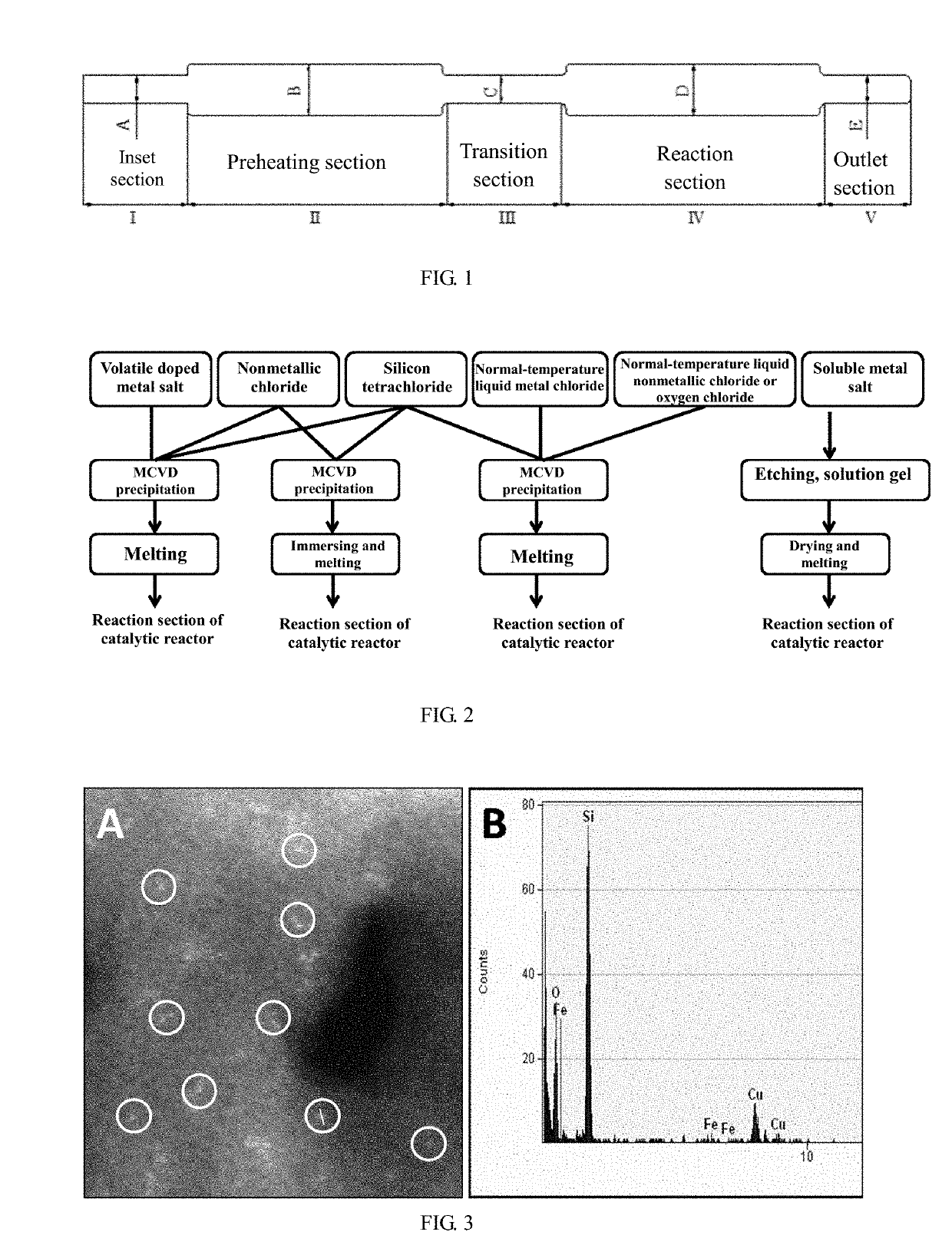
[0079]SiCl4 liquid and FeCl3 gas of 350° C. are brought into high temperature MCVD by using 30 mL / min of high purity helium; at 1650° C., SiCl4 and FeCl3 conduct high purity oxygen reaction on the inner wall of a quartz tube with an outer diameter of 20 mm (with a wall thickness of 1.5 mm) and a length of 150 mm for oxidization deposition for 30 minutes to obtain Fe doped SiO2 powder material; subsequently, under a temperature of 1980° C. and 2 bars of highly pure argon atmosphere, the material is melted for 40 minutes; then, a dopant thin layer with a thickness of 50 nm is formed on the inner wall of the reaction section; and the material is cooled naturally to obtain the reaction section B of a Fe© catalytic quartz reactor with a diameter of 20 mm and a length of 150 mm, wherein the doping amount of Fe is 0.6 wt. %.

Example

Embodiment 3

[0080]Modified Chemical Vapor Deposition (MCVD)

[0081]SiCl4 liquid and ZnCl2 gas of 750° C. are brought into high temperature MCVD by using 30 mL / min of high purity oxygen; at 1600° C., SiCl4 and ZnCl2 conduct oxidization deposition on the inner wall of a quartz tube with an outer diameter of 20 mm (with a wall thickness of 1.5 mm) and a length of 200 mm for 30 minutes to obtain Zn doped SiO2 powder material; subsequently, under a temperature of 2000° C. and 1.5 bars of highly pure helium atmosphere, the material is melted for 40 minutes; then, a dopant thin layer with a thickness of 50 nm is formed on the inner wall of the reaction section; and the material is cooled naturally to obtain the reaction section C of a Zn© catalytic quartz reactor with a diameter of 20 mm and a length of 200 mm, wherein the doping amount of Zn is 0.55 wt. %.


PUM

PropertyMeasurementUnit
Temperatureaaaaaaaaaa

Abstract

A reactor configuration comprises an inlet section I, a preheating section II, a transition section III, a reaction section IV and an outlet section V; except for the preheating section II and the reaction section IV, the existence of the inlet section I, the transition section III and the outlet section V depends on reaction conditions; and the process realizes no coke deposition synthesis of methane and high selectivity synthesis of ethylene. The methane conversion rate is 20-90%; ethylene selectivity is 65-95%; propylene and butylene selectivity is 5-25%; aromatic hydrocarbon selectivity is 0-30%; and coke deposition is zero.

Description

TECHNICAL FIELD[0001]The present invention relates to a catalytic reactor configuration, preparation and a method of direct synthesis of ethylene through oxygen-free catalysis of methane. The process realizes efficient conversion of methane, high selectivity synthesis of ethylene, high catalyst stability and zero carbon deposition.BACKGROUND[0002]Development and effective utilization of natural gas (methane) resource represent the development direction of the contemporary energy structure and is also one of important ways of ensuring sustainable development and energy greening. In recent years, western developed countries have made breakthrough in the development aspect of shale gas and “combustible ice”, resulting in a “shale gas revolution”. In China, shale gas resources have many types and are distributed centrally relatively. The recoverable resource potential is 25 trillion cubic meters (Qinghai-Tibet region excluded), which is equivalent to that of conventional natural gas for...

Claims


Application Information

Patent Timeline
IPC IPC(8): B01J7/00B01J10/00B01J19/02B01J19/00B01J19/24C07C2/76C23C16/40
CPCB01J7/00B01J10/007B01J19/02B01J19/0013B01J19/2415C07C2/76C23C16/402C07C2521/08C07C2521/18B01J8/02B01J2208/02C07C11/04B01J15/00C07C2/84B01J12/007B01J2219/00159B01J2219/0093B01J2219/00835Y02P20/52
Inventor BAO, XINHEGUO, XIAOGUANGFANG, GUANGZONGPAN, XIULIANMENG, JINGHENGYU, QINQINTAN, DALI
Owner DALIAN INST OF CHEM PHYSICS CHINESE ACAD OF SCI
Why Eureka
Try Eureka