
Gas Analyzer and Method for Measuring Nitrogen Oxides in an Exhaust Gas

a gas analyzer and nitrogen oxide technology, applied in the direction of machines/engines, separation processes, instruments, etc., can solve the problems of incomplete thermal decomposition of excess ozone and low concentration, and achieve reliable, continuous measurement of nitrogen oxides, and low equipment investment

Active Publication Date: 2019-10-17
SIEMENS AG
View PDF0 Cites 2 Cited by
  • Summary
  • Abstract
  • Description
  • Claims
  • Application Information

AI Technical Summary

Benefits of technology

The invention is a gas analyzer and method that can measuring nitrogen oxides in exhaust gases with low cost equipment. A special oxidation device is used to generate ozone, which is then used to measure nitrogen oxides in the exhaust gas. The device uses an ultraviolet light source, which is preferably a xenon excimer emitter. The gas analyzer also uses a closed reaction chamber where the exhaust gas flows through and the ultraviolet light source is placed. The performance of the ultraviolet light source can be improved by adding atmospheric oxygen or a plurality of tubes. The invention allows for a reliable and continuous measurement of nitrogen oxides in exhaust gases.

Problems solved by technology

Herein or as a result of disturbances, it is also possible that thermal decomposition of the excess ozone may be incomplete.
Here, once again the problem is encountered that, particularly with a high ozone generation rate, in addition to ozone, unwanted higher nitrogen oxides are generated, while, with a low ozone generation rate, the ozone concentration is too low, on the one hand, to effect rapid and complete conversion of nitrogen monoxide into nitrogen dioxide and, on the other, to keep dilution of the air to be measured to a minimum.

Method used


Image

  • Gas Analyzer and Method for Measuring Nitrogen Oxides in an Exhaust Gas
  • Gas Analyzer and Method for Measuring Nitrogen Oxides in an Exhaust Gas
  • Gas Analyzer and Method for Measuring Nitrogen Oxides in an Exhaust Gas

Examples


Embodiment Construction

[0036]Identical parts and parts with identical functions are given the same reference numbers in each case.

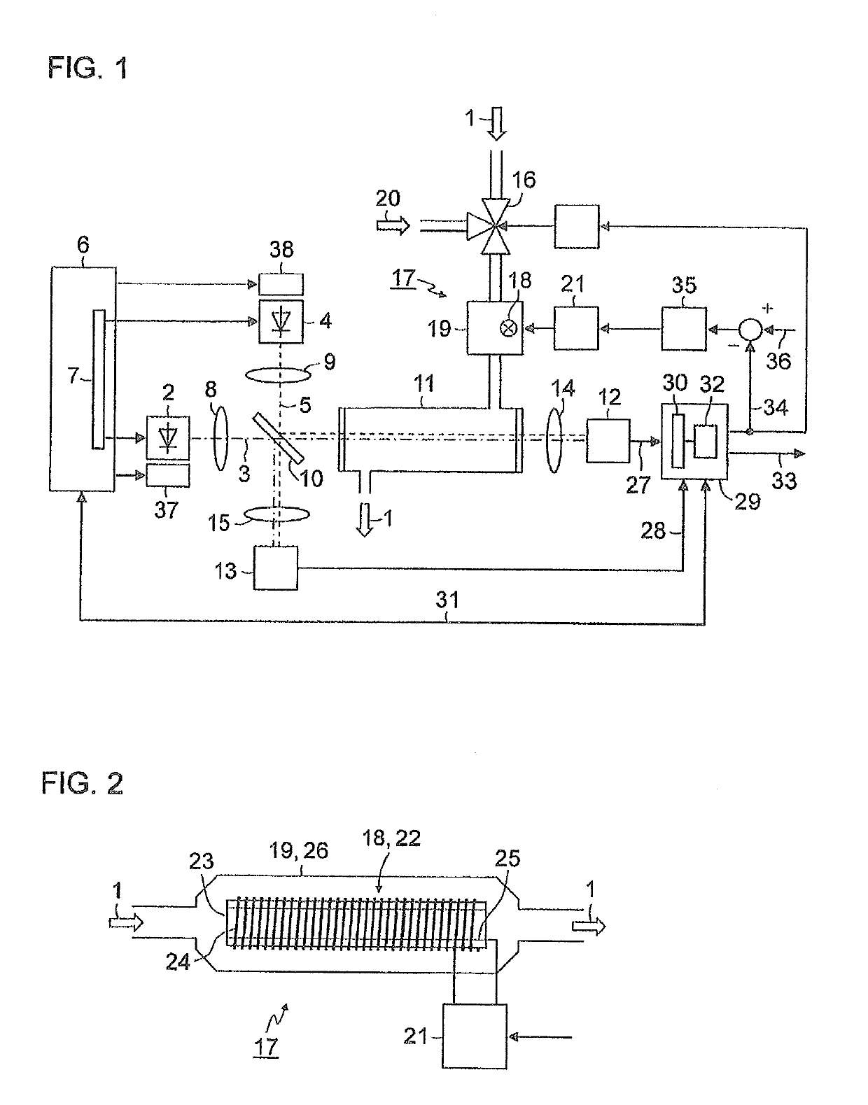
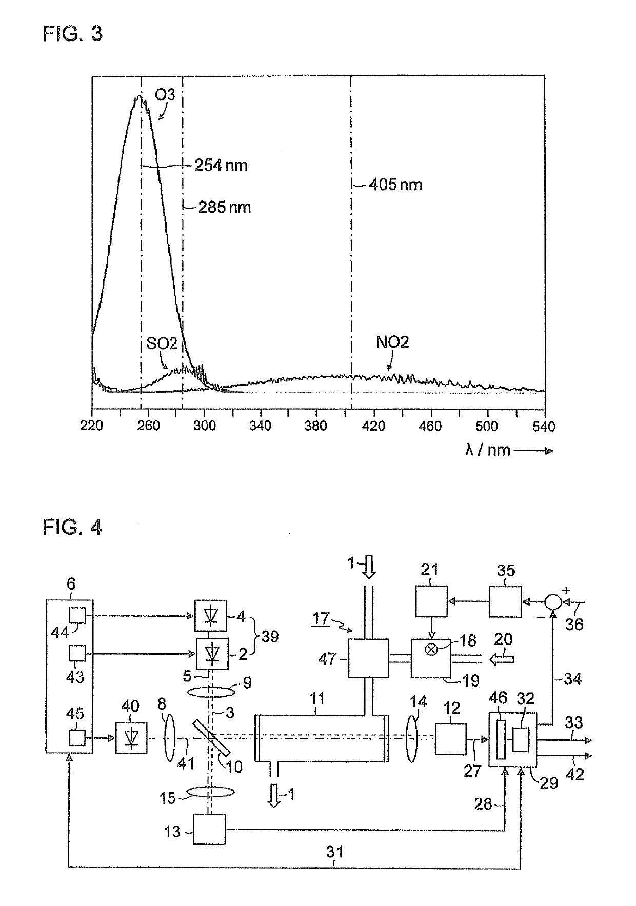
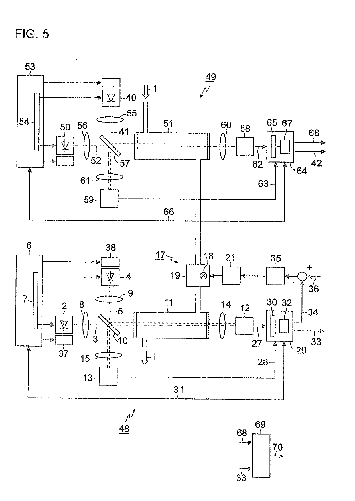
[0037]FIG. 1 is a simplified schematic representation of a block diagram of a gas analyzer for measuring nitrogen oxides in an exhaust gas 1. A first light-emitting diode 2 generates light 3 in the wavelength range of between 350 nm and 500 nm, for example, with a central wavelength of 405 nm. A second light-emitting diode 4 generates light 5 in the wavelength range of between 250 nm and 265 nm, for example, with a central wavelength of 254 nm. Both light-emitting diodes 2, 4 are actuated by a control device 6 which, in the exemplary embodiment depicted here, contains a multiplexer 7 in order to switch the light-emitting diodes 2, 4 on and off alternately. The light 3, 5 emitted by the light-emitting diodes 2, 4 is shaped via collimator lenses 8, 9 into parallel light bundles (hereinafter, called light beams) and supplied to a beam splitter 10, preferably a “polka-dot” beam spl...


PUM

PropertyMeasurementUnit
Nanoscale particle sizeaaaaaaaaaa

Abstract

Gas analyzer and method for measuring nitrogen oxides in an exhaust gas, wherein to measure the nitrogen oxides, ozone is generated from oxygen, the exhaust gas is treated with the ozone generated to convert nitrogen monoxide within the exhaust gas into nitrogen dioxide, the nitrogen dioxide concentration in the treated exhaust gas is measured photometrically using a first light-emitting diode which emits with a central wavelength between 350 nm and 500 nm and output as the nitrogen oxide concentration in the exhaust gas, and the ozone concentration in the treated exhaust gas is measured photometrically using a second light-emitting diode which emits with a central wavelength between 250 nm and 265 nm, where generation of the ozone using the measured ozone concentration as an actual value is regulated to a prespecified setpoint value to enable reliable continuous measurement of nitrogen oxides in exhaust gases with a low outlay on equipment.

Description

BACKGROUND OF THE INVENTION1. Field of the Invention[0001]The invention relates to a gas analyzer for measuring nitrogen oxides in an exhaust gas with an oxidation device, which comprises an ozone generator for the generation of ozone from oxygen and is embodied to treat the exhaust gas with the ozone in order to convert nitrogen monoxide contained in the exhaust gas into nitrogen dioxide, a first light-emitting diode that emits with a central wavelength of between 350 nm and 500 nm, a second light-emitting diode that emits with a central wavelength of between 250 nm and 265 nm, a measuring chamber through which the treated exhaust gas flows and the light from the first light-emitting diode and the light from the second light-emitting diode passes, a detector that detects the light from the first light-emitting diode and the light from the second light-emitting diode after it has passed through the measuring chamber and which generates a detector signal with a first signal component...

Claims


Application Information

Patent Timeline
IPC IPC(8): G01N33/00G01N31/00G01N21/31F01N11/00
CPCG01N33/0037G01N31/005G01N21/3151F01N11/00G01N21/3504G01N21/3518G01N21/01G01N2021/0106G01N21/33G01N33/0009G01N2201/062F01N2560/026F01N2560/12B01D53/30B01D53/56B01D2251/104G01N33/0013Y02T10/40Y02A50/20
Inventor HEFFELS, CAMIELROSSFELD, DANIEL
Owner SIEMENS AG
Learn More