
Acoustically excited encapsulated microbubbles and mitigation of biofouling

a technology of encapsulated microbubbles and encapsulated microbubbles, which is applied in the direction of cleaning using liquids, membranes, lighting and heating apparatus, etc., can solve the problems of reducing the ability of feed water to dislodge biofilms, and reducing the resilience of biofilms. surface and difficult to remove. , to achieve the effect of increasing the sonication

Active Publication Date: 2019-11-28
KING ABDULLAH UNIV OF SCI & TECH
View PDF3 Cites 8 Cited by
  • Summary
  • Abstract
  • Description
  • Claims
  • Application Information

AI Technical Summary

Benefits of technology

The present patent pertains to a technology for preventing and removing biofilms in membrane filtration systems. The technology involves using acoustically excited encapsulated microbubbles to disrupt biofilms by sonicating them. The encapsulated microbubbles are embedded in the biofilm and sonication causes them to release lipid, protein, or other substances that bind to the extracellular polymeric substances (EPS) in the biofilm, leading to its disruption. The technology can also be used to recycle the retentate solution containing the disrupted biofilm by increased sonication and sonoluminescence, killing microorganisms from the uprooted biofilm near the microbubbles. The patent provides a versatile method for preventing and removing biofilms in membrane filtration systems.

Problems solved by technology

Thus, biofilm structural integrity, adhesiveness and elasticity make biofilms resilient and difficult to remove from surfaces.
Biofilm formation, which occurs frequently in membrane filtration systems, causes biofouling, which is an unacceptable decline in membrane performance.
Additionally, a hydrodynamic boundary layer generally exists adjacent to the biofilm which reduces the flow of the feed water over the biofilm, thereby decreasing the ability of the feed water to dislodge the biofilm.
Biofouling is a major problem in all membrane filtration systems, for example accounting for about 35% of membrane failures in reverse osmosis (RO) plants.
Thus, biofouling presents significant challenges and costs wherever it occurs, but especially in membrane filtration systems.
There are several historical limitations involved with the application, use and manufacture of known membrane processes.
A major disadvantage involved with the use of known membranes, especially in water- and wastewater-treatment processes, is that the long-term reliability has not completely been proven.
Membrane processes sometimes require excessive pretreatment due to their sensitivity to concentration polarization, chemical interaction with water constituents, and membrane fouling.
And, membranes have historically been mechanically unreliable and non-robust, which means membranes can easily be destroyed by a malfunction in the operating procedure.
In certain applications, such as the purification of industrial effluents and wastewaters or the desalination of brackish water, there may be a problem with the disposal of the concentrate.
Although membrane biofouling is common, there has been very limited success in prevention or remediation of biofouling due to membrane sensitivity to chemical / biological processes, site-specific feed water quality issues, and the like.
In the prior art, no universal technology exists that can be applied to all sorts of feed water, as feed water quality varies in terms of bacteria levels, pH and in the analysis of both organic and inorganic compounds.
One conventional approach to biofouling control includes the use of biocides and disinfectants, which have achieved very limited success.
Chlorine as a disinfectant is widely applied in water treatment, but it has significant limitations in membrane systems.
Polymeric membranes, which are commonly used in water treatment, are prone to chemical oxidation and degradation by chlorine; thus, in such uses, chlorine must be removed from the feed water prior to entering the membrane section, and chlorine fails to reach bacterial colonies on the membrane.
Dose rates and application costs for these chemicals are high and are not approved for online dosing in potable applications.
Furthermore, these available biocide products are unable to adequately penetrate biofilm layers and lyse / dissolve the foulants within the biofilm.
In practice, such processes are inadequate to remove biomass from membrane surfaces.
These procedures require plugging of the feed path, which restricts transport of the chemicals into the blocked region.
The use of cleaning-in-place is further limited due to several factors, such as mechanical interaction, cost, incorrect chemical selection, inability to penetrate the biofilm layer, poor cleaning practice (with respect to parameters such as pH, temperature, contact time or improper recirculation flow rates) and delays in application.
Current use of membrane technologies, such as microfiltration (MF) or ultrafiltration (UF), has been used for pretreatment with reverse osmosis (RO) systems with little success.
These techniques are rarely 100% efficient, and a small percentage of viable bacteria pass through the pretreatment membranes to the RO system, and the MF / UF filtration systems themselves are also susceptible to biofouling.

Method used


Image

  • Acoustically excited encapsulated microbubbles and mitigation of biofouling
  • Acoustically excited encapsulated microbubbles and mitigation of biofouling
  • Acoustically excited encapsulated microbubbles and mitigation of biofouling

Examples


example 1

[0077]Example 1 is a general use description of the claimed method. The method is useful in a variety of membrane filtration systems including reverse osmosis systems, microfiltration systems, ultrafiltration systems, nano-filtration systems, forward osmosis systems, and membrane distillation systems. The membrane filtration system can be in any configuration (e.g., spiral wound, tubular, hollow fiber, flat sheet, etc.). The membrane filtration system can be submerged or pressurized. Microbubbles used in the present invention are usually sized less than 1 micrometer (μm), and preferably range from 5-50 microns in diameter size or from 0.5 μm to 10 μm for use in the present invention. Membrane thicknesses (while they depend on the system implementation) will range from 0.01 microns to 1000 microns, with 0.1 microns to 10 micron being a preferred thickness range for this example.

[0078]For this example, one or more filtrate and retentate ports are used, with each being sized approximat...

example 2

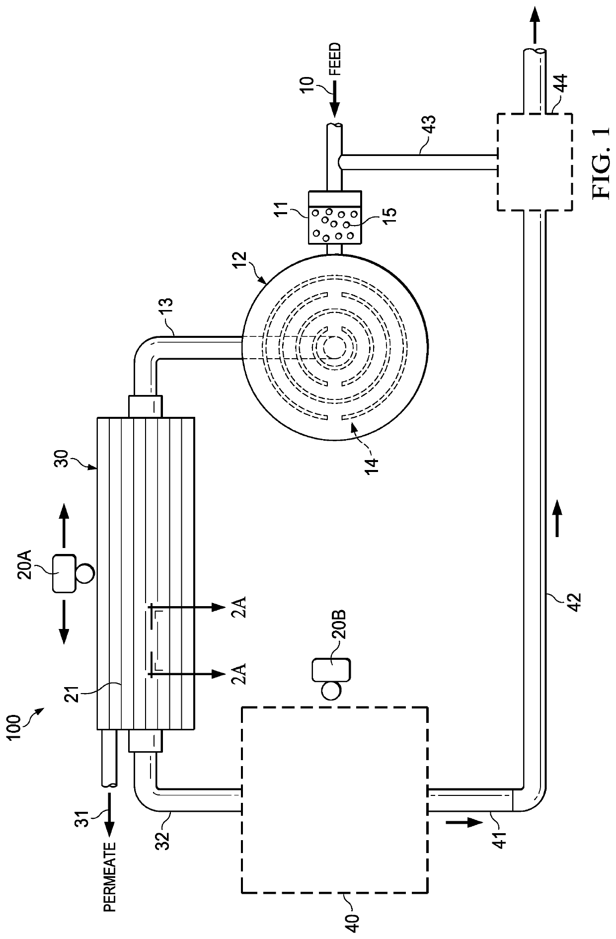
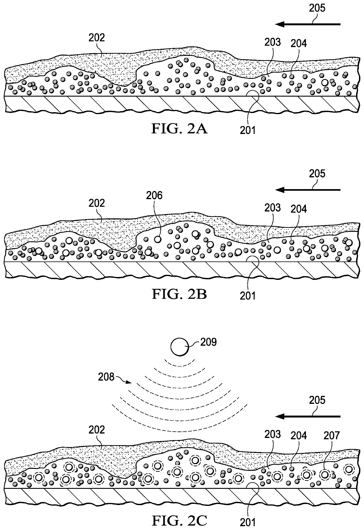
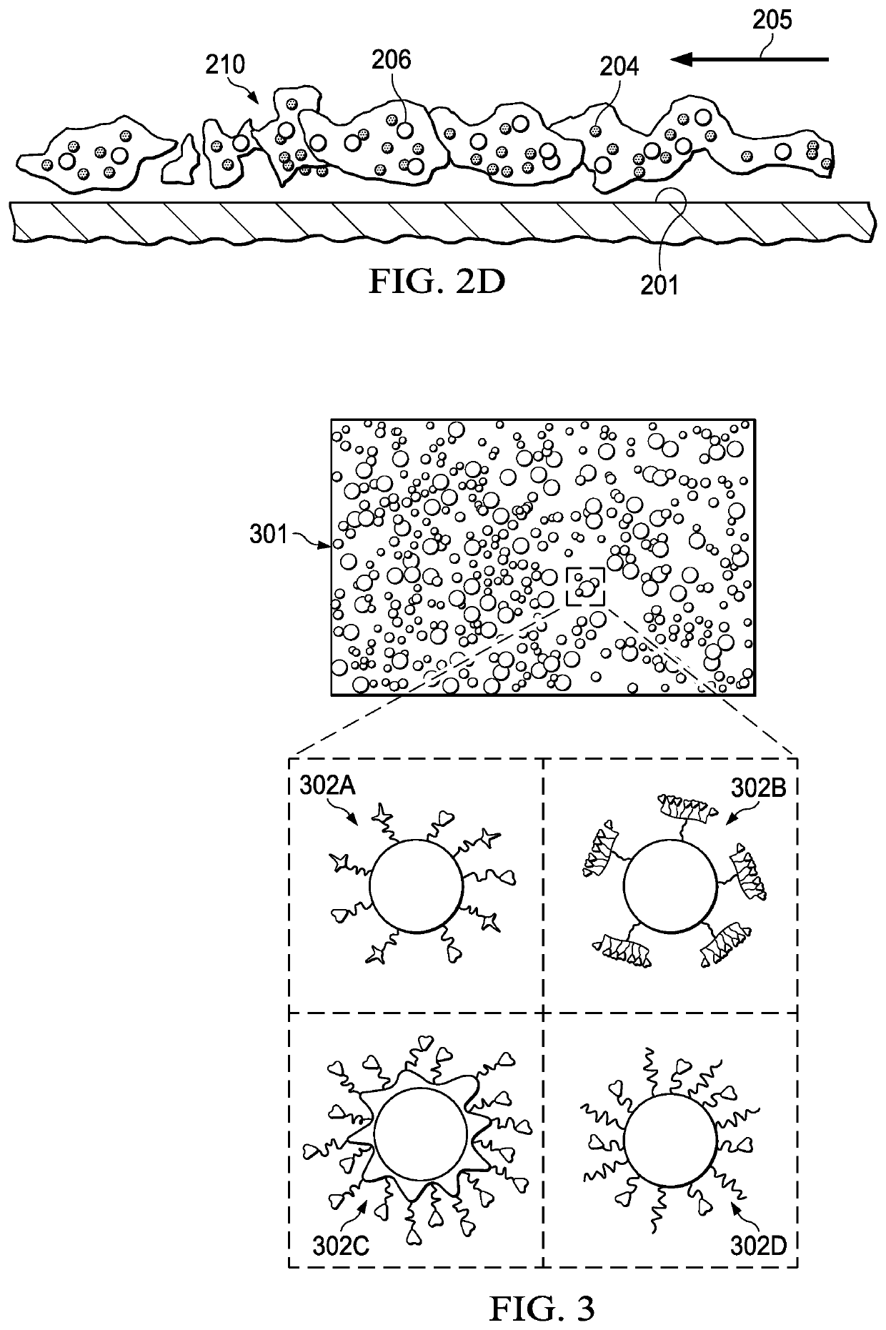
[0086]Example 2 is directed to a method of using the membrane filtration system and membranes of FIGS. 1 and 2A-2D, and reference numerals herein refer to the same elements depicted in FIGS. 1 and 2A-2D. This method is useful regardless of the quality of the feed source. The feed solution may be selected from the group consisting of fresh water, ground water, brackish water, sea water, waste water, and industrial water. By way of example, the methods provided herein for Example 2 are for water desalination and water reclamation / reuse systems.

[0087]As shown in FIG. 1, water in need of treatment, such as brackish water used in this example, enters the membrane filtration system (100) as part of the feed solution stream (10). Encapsulated microbubbles (15) having a compressed gas core with one or more ligands on the encapsulation shell that are selected for the specific type of EPS in the brackish water are synthesized in the microbubble production unit (11). The feed solution stream (...


PUM

PropertyMeasurementUnit
thicknessaaaaaaaaaa
thicknessaaaaaaaaaa
operating pressureaaaaaaaaaa

Abstract

Provided herein is a universally applicable biofouling mitigation technology using acoustically excited encapsulated microbubbles that disrupt biofilm or biofilm formation. For example, a method of reducing biofilm formation or removing biofilm in a membrane filtration system is provided in which a feed solution comprising encapsulated microbubbles is provided to the membrane under conditions that allow the encapsulated microbubbles to embed in a biofilm. Sonication of the embedded, encapsulated microbubbles disrupts the biofilm. Thus, provided herein is a membrane filtration system for performing the methods and encapsulated microbubbles specifically selected for binding to extracellular polymeric substances (EFS) in a biofilm.

Description

RELATED APPLICATION DATA[0001]This application claims the benefit of U.S. Provisional Patent Application Ser. No. 62 / 299,956, filed Feb. 25, 2016.TECHNICAL FIELD[0002]The present invention relates to a method and system for preventing biofilm formation or removing biofilm.BACKGROUND OF THE INVENTION[0003]The background of this invention will address biofilm formation and removal, as well as membrane technology matters.[0004]Biofilm Formation and Biofouling[0005]Microorganisms are microscopic living organisms that are found in all areas of the biosphere in enormous numbers. Bacteria make up a large portion of these microorganisms and are among the most abundant organisms on earth. Bacteria possess a wide range of metabolic versatility and adaptability allowing them to thrive in many circumstances where other organisms could not survive.[0006]Bacteria can exist as individual organisms, but the majority live in colonies consisting of an aggregation of numerous bacterial organisms. One ...

Claims


Application Information

Patent Timeline
Patent Type & Authority Applications(United States)
IPC IPC(8): A61L2/025B01D65/02B01D65/08B01J13/04
CPCA61L2/025B01D65/02B01J13/04B01D2311/25B01D61/20B01D2311/04B01D61/10B01D65/08B01D2321/2075B01D2321/18B01D2315/20B08B3/12B01D61/368B08B3/102B08B17/00F28F19/00F28G7/00F28G13/00B01D2321/35
Inventor QAMAR, ADNANFORTUNATO, LUCALEIKNES, TOROVE
Owner KING ABDULLAH UNIV OF SCI & TECH
Learn More