
Methods for 3D printing of poly-4-hydroxybutyrate and copolymers

a technology of polyhydroxybutyrate and polymer, applied in the direction of additive manufacturing process, prosthesis, catheter, etc., can solve the problems of not disclosing equipment not disclosing equipment, etc., to improve the print quality of objects, reduce the molecular weight of polymers, and rapid solidification of polymers

Active Publication Date: 2019-12-12
TEPHA INC
View PDF0 Cites 29 Cited by
  • Summary
  • Abstract
  • Description
  • Claims
  • Application Information

AI Technical Summary

Benefits of technology

The patent describes a method for 3D printing objects using poly-4-hydroxybutyrate and copolymers thereof. The method involves using new printers and improved processing conditions to allow for continuous printing without interruptions. The method also includes maintaining a uniform temperature across the printing stage and allowing for rapid solidification of the polymer to form the printed object. The new method achieves print lines that are within 10% of the expected dimensions and results in high-quality printed objects.

Problems solved by technology

Crump does not disclose equipment suitable for FFF of a thermoplastic, such as P4HB, that must be heated to more than twice its melt temperature in order for the polymer to flow, that has a low softening temperature, and that solidifies slowly from the melt.
Church also does not disclose equipment suitable for FFF of a thermoplastic like P4HB that must be heated to at least twice its melt temperature in order for the polymer to flow, that has a low softening temperature, and that solidifies slowly from the melt.
Church et al. do not disclose equipment for FFF comprising a shroud fixed to the print head, a heat shield, an insulator to prevent contact of the heat shield and hot end, and a cooled flat print stage.
Thus, there is currently no disclosure of how P4HB and copolymers thereof can be processed by 3D printing including the equipment and conditions necessary for continuous printing of high quality objects.
There is also no disclosure of how to prevent significant drops in the molecular weight of P4HB and copolymers thereof during printing.

Method used


Image

  • Methods for 3D printing of poly-4-hydroxybutyrate and copolymers
  • Methods for 3D printing of poly-4-hydroxybutyrate and copolymers
  • Methods for 3D printing of poly-4-hydroxybutyrate and copolymers

Examples


example 1

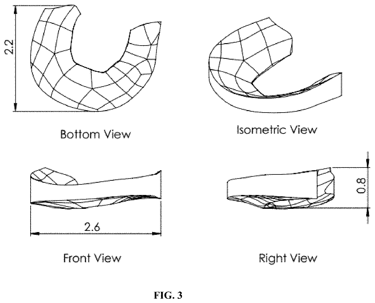
l 3D Printing of a P4HB Meniscal Implant by FFF

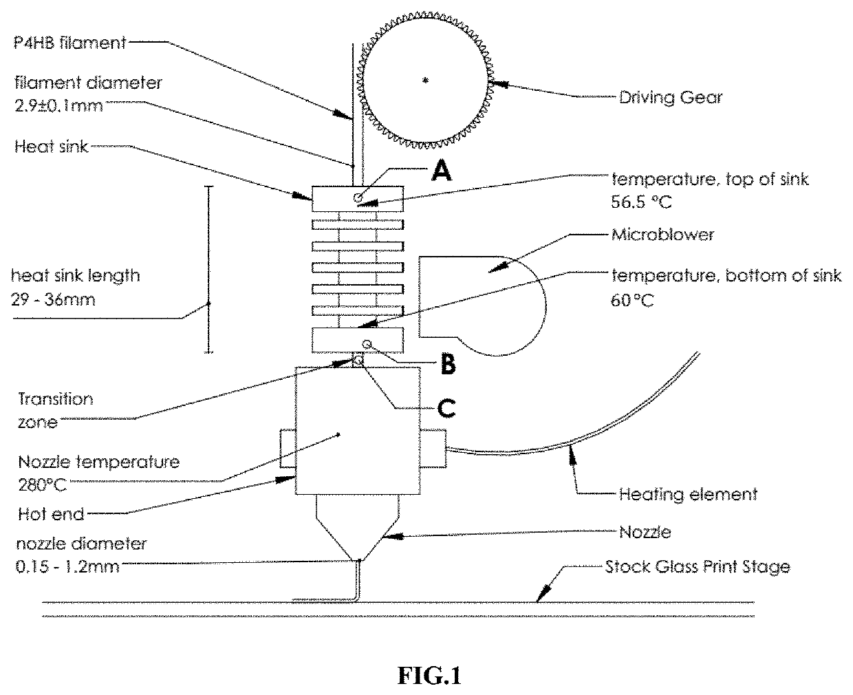
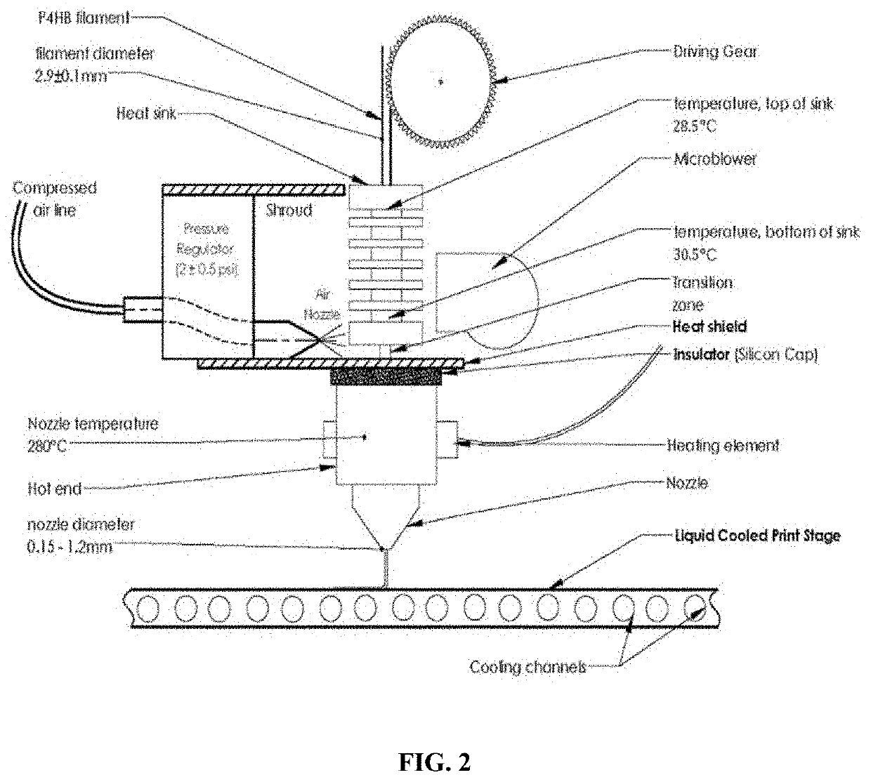
[0145]In this example, the same setup parameters were used as in Comparative Example 1 above. However, multiple modifications were made to the 3D printer as follows. A shroud was attached to the printer head which incorporated a compressed air line and nozzle to focus cooling air on the lowest fin of the heat sink. A heat shield was located in the transition zone between the hot end and the heat sink to prevent the compressed air from hitting the hot end and printing stage. An insulator, made from silicon, was located between the hot end and the heat shield to protect the heat shield from thermal deformation. And, the printing stage was replaced with an aluminum stage that could be cooled, and that had a flatter surface. The stage was maintained at 22° C. during printing. The modified equipment set up is shown in FIG. 2.

[0146]P4HB filament with an average diameter of 2.85 mm, and a polymer Mw of 340 kDa, was used for printing. Directing...

example 2

ng of a P4HB Mesh by FFF

[0148]A P4HB mesh with a crisscross pattern was printed with the FFF 3D printer set up shown in FIG. 2 using the following method. The desired crisscross pattern, with a line to line distance of 2 mm and consecutive layers set at 45 degrees to each other, was transformed into an STL file, and rendered into a two-slice 3D printing profile (Matter Control) with a slice (layer) height of 0.25 mm. Unoriented P4HB monofilament (Mw=340 kDa) with an average diameter of 2.85 mm was fed into the printer at a feed rate of 0.22 mm / s, heated in the hot end to a temperature of 270° C., and printed from a nozzle with an orifice diameter of 0.3 mm and a print speed of 6.5 mm / s. The stage was made from aluminum, and was maintained at a temperature of 22° C. during printing. Adhesion of the first printed layer to the aluminum stage was excellent, and very uniform as shown in FIG. 7A. The temperature at the bottom of the heat sink was maintained at 30° C. by directing compress...

example 3

ng of P4HB by Fused Pellet Deposition (FPD)

[0149]A P4HB object was printed by FPD using the equipment set up shown in FIG. 8A comprising a reservoir with a heated jacket and a pressure line and cap, a nozzle located at the bottom of the reservoir, and a moving stage. The reservoir was charged with P4HB pellets (Mw 150 kDa), pressurized with compressed air to a pressure of 9 bars (900 kPa), and the pellets were heated to 120° C. Under these conditions, it was possible to print good quality objects comprising P4HB when the diameter of the orifice in the printer nozzle was 0.2 mm (FIG. 8B; right). When the temperature exceeded 180° C., the printed structure warped and had poor resolution (FIG. 8B; middle and left).


PUM

PropertyMeasurementUnit
Temperatureaaaaaaaaaa

Abstract

Methods to fabricate objects by 3D printing of poly-4-hydroxybutyrate (P4HB) and copolymers thereof have been developed. In one method, these objects are produced by continuous fused filament fabrication using an apparatus and conditions that overcome the problems of poor feeding of the filament resulting from the low softening temperature of the filament and heat creep along the fed filament. Methods using an apparatus including a heat sink, a melt tube, a heating block and nozzle, and a transition zone between the heat sink and heating block, with the melt tube extending through the heat sink, transition zone, and heat block to the nozzle are disclosed. 3D objects are also printed by fused pellet deposition (FPD), melt extrusion deposition (MED), selective laser melting (SLM), printing of slurries and solutions using a coagulation bath, and printing using a binding solution and polymer granules.

Description

CROSS-REFERENCE TO RELATED APPLICATIONS[0001]This application claims benefit of U.S. Provisional Application No. 62 / 683,407, filed Jun. 11, 2018, hereby incorporated herein by reference in its entirety.FIELD OF THE INVENTION[0002]The present invention generally relates to methods for fabricating objects by 3D printing of poly-4-hydroxybutyrate (P4HB), copolymers and blends thereof, equipment and conditions that allow continuous printing of these objects, and the use of these methods to produce medical implants for uses that include plastic and reconstructive surgery including mastopexy and breast reconstruction, general surgery including hernia repairs and anti-adhesion devices, tissue engineering, drug delivery, pelvic floor reconstruction, treatment of stress urinary incontinence, nerve repair, periodontal surgery, oral surgery, orthopedic surgery, stenting, vascular and cardiovascular surgery.BACKGROUND OF THE INVENTION[0003]3D Printing is a computer controlled process whereby a ...

Claims


Application Information

Patent Timeline
IPC IPC(8): B29C64/118B29C64/209B29C64/295B29C64/393B29C64/321B29C64/227B29C64/153B29C64/268A61L27/14A61L29/06
CPCB29C64/295B29C64/321B33Y70/00B29C64/393B33Y10/00B29K2067/04B29C64/268B29C64/153B33Y30/00B29C64/118B29C64/227A61L27/14A61L29/06B33Y50/02B29C64/209B29C64/112B29C64/165B29C64/255B33Y80/00A61L31/06A61L27/54A61L29/16A61L31/16A61L2300/404A61L27/18C08L67/04B29C64/106B33Y70/10
Inventor LIMEM, SKANDERHARUN, RESHAD BINDUBOIS, MATTHEWMARTIN, DAVID P.RIZK, SAID
Owner TEPHA INC
Learn More