Spin-orbit torque (SOT) magnetic tunnel junction (MTJ) (sot-mtj) devices employing perpendicular and in-plane free layer magnetic anisotropy to facilitate perpendicular magnetic orientation switching, suitable for use in memory systems for storing data

a technology of spin-orbit torque and magnetic tunnel junction, which is applied in the direction of magnetic bodies, instruments, substrate/intermediate layers, etc., can solve the problems of low density and high cost, low power density, and insufficient fast and low-power stt-mram devices to directly replace sram for high-performance computing applications, etc., to facilitate perpendicular magnetic orientation switching, reduce switching energy, and facilitate sot switching

Active Publication Date: 2020-02-27
QUALCOMM INC
View PDF4 Cites 17 Cited by
  • Summary
  • Abstract
  • Description
  • Claims
  • Application Information

AI Technical Summary

Benefits of technology

[0011]Aspects disclosed herein include spin-orbit torque (SOT) magnetic tunnel junction (MTJ) (SOT-MTJ) devices employing perpendicular and in-plane free layer magnetic anisotropy to facilitate perpendicular magnetic orientation switching. A SOT-MTJ device facilitates SOT switching to reduce switching energy, increase switching speed, and increase endurance of the MTJ in the SOT-MTJ device. In one example, a free layer in a MTJ in the SOT-MTJ device includes both a perpendicular magnetic anisotropy (PMA) region(s) and an in-plane magnetic anisotropy (IMA) region(s). The PMA region(s) in the free layer of the SOT-MTJ device provides for the free layer of the MTJ to have a magnetic anisotropy. A spin torque can be generated in the free layer of the MTJ by directing a SOT switching current to flow through an electrode adjacent to the free layer sufficient to switch the magnetic moment of the free layer from a perpendicular magnetic orientation to an in-plane magnetic orientation. To prevent the in-plane magnetic orientation from returning to a non-deterministic perpendicular magnetic orientation (e.g., either zero (0) or one hundred eighty (180) degrees), after the SOT switching current is removed, the free layer of the MTJ also includes the IMA region(s) to provide an in-plane magnetization in the MTJ to generate an effective magnetic field in the free layer. This magnetic field assists in switching the magnetic moment of the free layer past an in-plane magnetic orientation to a perpendicular magnetic orientation in response to application of the SOT switching current to achieve deterministic switching for the SOT-MTJ device. Thus, as an example, an external magnetic field may not be required to be applied to the free layer of the MTJ during a switching operation to switch the magnetic orientation to a perpendicular magnetic orientation to achieve deterministic switching for the SOT-MTJ device. This mixture of PMA and IMA regions in the free layer of a SOT-MTJ device can achieve high-speed switching like a static random access memory (SRAM) device, yet the SOT-MTJ device can still be a non-volatile memory device for data retention over power cycles.
[0015]In another exemplary aspect, a magneto-resistive random access memory (MRAM) bit cell is provided. The MRAM bit cell comprises an access transistor comprising a gate coupled to a word line, a source, and a drain. The MRAM bit cell also comprises a SOT-MTJ device. The SOT-MTJ device comprises a bottom electrode comprised of a metal material disposed above a substrate. The SOT-MTJ device also comprises a top electrode comprised of a metal material disposed above the bottom electrode. The SOT-MTJ device also comprises a MTJ. The MTJ comprises a tunnel barrier disposed above the substrate. The MTJ also comprises a pinned layer comprising a ferromagnetic material having a fixed PMA, the pinned layer disposed adjacent to a first side of the tunnel barrier. The MTJ also comprises a free layer comprising a ferromagnetic material disposed adjacent to a second side of the tunnel barrier opposite of the first side of the tunnel barrier. The free layer comprises at least one PMA region having a free magnetization in a perpendicular orientation to the substrate, and at least one IMA region having a fixed magnetization in an in-plane orientation to the substrate. An electrode among the bottom electrode or the top electrode is coupled to the source or the drain of the access transistor, and the other electrode among the bottom electrode or the top electrode is coupled to a bit line. The electrode among the bottom electrode or the top electrode is configured to receive an in-plane current flowing in-plane to the bottom electrode in response to a write signal applied to the word line indicating a write active state to cause the access transistor to be activated, to generate a SOT to induce spin accumulation at an interface between the bottom electrode and the free layer to switch the magnetization of the free layer to an in-plane orientation. The at least one IMA region of the free layer of the MTJ induces a magnetic field in the free layer to assist in the switching of the magnetization of the at least one PMA region in the free layer to the perpendicular orientation in response to the in-plane current.

Problems solved by technology

Conventional SRAM-based cache is very fast, but it has low density and expensive costs.
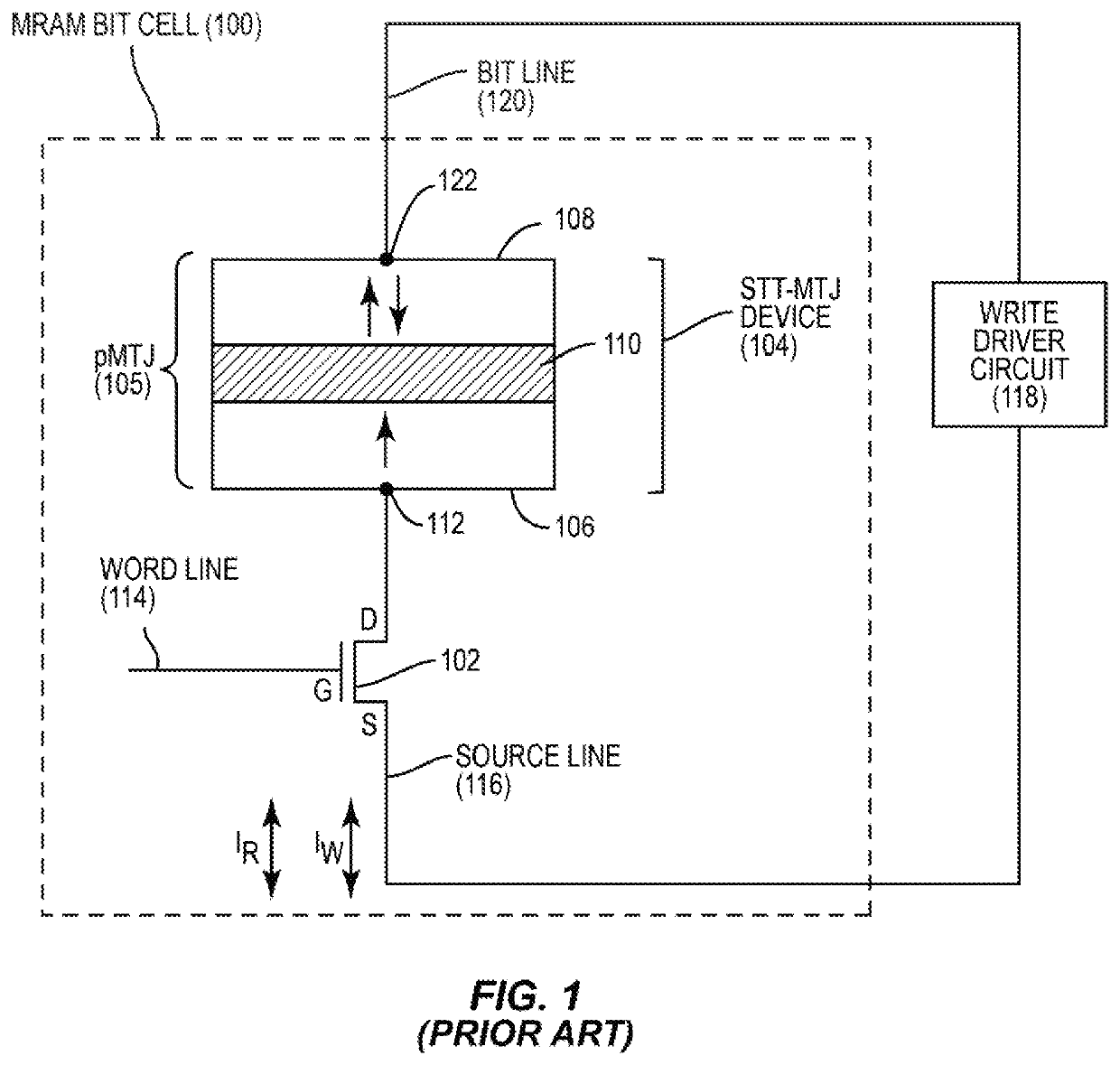
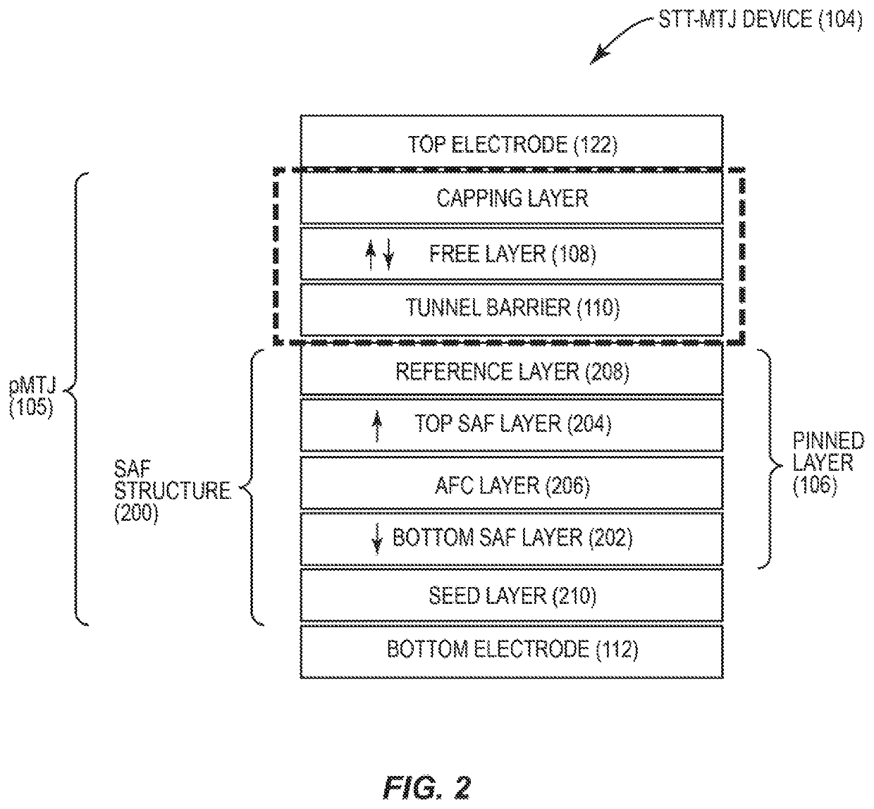
Though STT-MRAM devices like the STT-MTJ device 104 in FIGS. 1 and 2 have shown promise for providing unified memory for low-power processor-based applications, STT-MRAM devices may not be fast and low-power enough to directly replace SRAM for high-performance computing applications (e.g., high-level caches).
Furthermore, fast STT-MRAM switching may suffer from penalties in read performance, cycling endurance, or data retention.
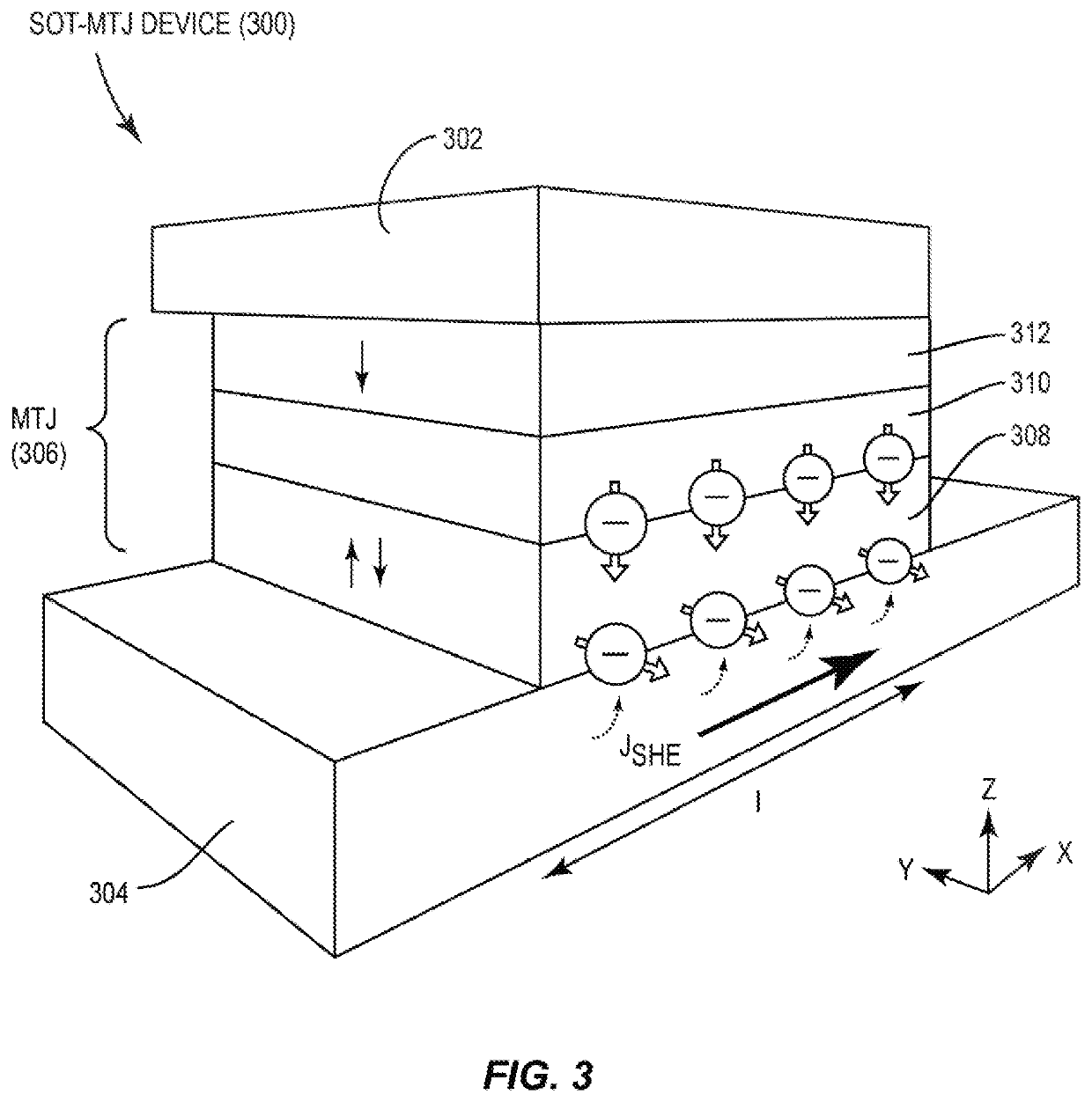
To provide for deterministic switching in the SOT-MTJ device 300, an external magnetic field can be applied to the free layer 308 of the MTJ 306 during a switching operation to assist the magnetic moment of the free layer 308 to switch past an in-plane magnetic orientation to either a zero (0) degree or one hundred eighty (180) degrees perpendicular magnetic orientation depending on the direction of the external magnetic field or the direction of the in-plane current I. However, application of an external magnetic field may be difficult or not feasible to provide for certain applications of the SOT-MTJ device 300.

Method used


Image

  • Spin-orbit torque (SOT) magnetic tunnel junction (MTJ) (sot-mtj) devices employing perpendicular and in-plane free layer magnetic anisotropy to facilitate perpendicular magnetic orientation switching, suitable for use in memory systems for storing data
  • Spin-orbit torque (SOT) magnetic tunnel junction (MTJ) (sot-mtj) devices employing perpendicular and in-plane free layer magnetic anisotropy to facilitate perpendicular magnetic orientation switching, suitable for use in memory systems for storing data
  • Spin-orbit torque (SOT) magnetic tunnel junction (MTJ) (sot-mtj) devices employing perpendicular and in-plane free layer magnetic anisotropy to facilitate perpendicular magnetic orientation switching, suitable for use in memory systems for storing data

Examples


Embodiment Construction

[0028]With reference now to the drawing figures, several exemplary aspects of the present disclosure are described. The word “exemplary” is used herein to mean “serving as an example, instance, or illustration.” Any aspect described herein as “exemplary” is not necessarily to be construed as preferred or advantageous over other aspects.

[0029]Aspects disclosed herein include spin-orbit torque (SOT) magnetic tunnel junction (MTJ) (SOT-MTJ) devices employing perpendicular and in-plane free layer magnetic anisotropy to facilitate perpendicular magnetic orientation switching. A SOT-MTJ device facilitates SOT switching to reduce switching energy, increase switching speed, and increase endurance of the MTJ in the SOT-MTJ device. In one example, a free layer in a MTJ in the SOT-MTJ device includes both a perpendicular magnetic anisotropy (PMA) region(s) and an in-plane magnetic anisotropy (IMA) region(s). The PMA region(s) in the free layer of the SOT-MTJ device provides for the free layer ...


PUM

PropertyMeasurementUnit
perpendicular magnetic anisotropyaaaaaaaaaa
free magnetizationaaaaaaaaaa
magnetic anisotropyaaaaaaaaaa

Abstract

Aspects disclosed include spin-orbit torque (SOT) magnetic tunnel junction (MTJ) (SOT-MTJ) devices employing perpendicular and in-plane free layer magnetic anisotropy to facilitate perpendicular magnetic orientation switching. A free layer in a MTJ in the SOT-MTJ device includes both a perpendicular magnetic anisotropy (PMA) region(s) and an in-plane magnetic anisotropy (IMA) region(s). A spin torque is generated in the free layer when a SOT switching current flows through an electrode adjacent to the free layer sufficient to switch the magnetic moment of the free layer to an in-plane magnetic orientation. To prevent a non-deterministic perpendicular magnetic orientation after the SOT switching current is removed, the free layer also includes the IMA region(s) to provide an in-plane magnetization to generate an effective magnetic field in the free layer to assist in switching the magnetic moment of the free layer past an in-plane magnetic orientation to a perpendicular magnetic orientation.

Description

BACKGROUNDI. Field of the Disclosure[0001]The technology of the disclosure relates generally to switching of magnetic orientation in magnetic tunnel junctions (MTJs), wherein the MTJs can be employed in memory bit cells in a memory system to store a memory state as a function of the stored magnetic orientation.II. Background[0002]Semiconductor storage devices are used in integrated circuits (ICs) in electronic devices to provide data storage. One example of a semiconductor storage device is static random access memory (SRAM). Conventional SRAM-based cache is very fast, but it has low density and expensive costs. To resolve the disadvantage of SRAM cache, magneto-resistive random access memory (MRAM) can be employed in memory to provide data storage. MRAM is non-volatile memory in which data is stored by programming a magnetic tunnel junction (MTJ) as part of an MRAM bit cell. One advantage of MRAM is that MTJs in MRAM bit cells can retain stored information even when power is turned...

Claims


Application Information

Patent Timeline
Patent Type & Authority Applications(United States)
IPC IPC(8): H01L43/02H01L43/10H01L43/12H01F10/32G11C11/16H01L27/22
CPCH01F10/3286H01L43/10G11C11/1675G11C11/1657H01L43/12H01L43/02G11C11/161H01L27/228H01F10/3254G11C11/1673H01F10/3272H01F10/329H10B61/22H10N50/01H10N50/85H10N50/10H10N50/80
Inventor PARK, CHANDOKIM, SUNGRYULKANG, SEUNG HYUK
Owner QUALCOMM INC
Why Eureka
Try Eureka