Holographic Imaging Device and Data Processing Method Therefor

a holographic imaging and data processing technology, applied in the field of digital holography, can solve the problems of not exceeding the half wavelength of light, difficult to improve performance and function, and difficult to improve resolution, and achieve the effects of simple structure, simple structure and easy handling

Active Publication Date: 2020-08-20
UNIV OF HYOGO
View PDF1 Cites 3 Cited by
  • Summary
  • Abstract
  • Description
  • Claims
  • Application Information

AI Technical Summary

Benefits of technology

[0020]The resolution of the usual optical microscope cannot exceed the light half-wavelength, namely, the diffraction limit of light. As a microscope that exceeds such a resolution limit, there is a structured illumination microscope (SIM) using the moire effect. SIM has a number of problems associated with the use of objective lenses compared to lens-less holographic microscopes. In addition, SIM is expensive, has a complicated structure and is not easy to handle, and fur

Problems solved by technology

However, in imaging techniques and microscopes as described in the above-mentioned patent documents 1, 2, and 3, the resolution can not exceed the half wavelength of light as well as in the conventional optical microscope.
This simultaneous recording condition is a great limitation for the microscope using this technology, and makes it difficult to improve the performance and function.
The microscope as described in non-patent document 2 has a problem that the object to be photographed is limited to a sample that can be rotated at the time of photographing, and it is considered that noise caused by the positional change, for rotating the sample, makes it difficult to improve the resolution.
Since the microscope of non-patent doc

Method used


Image

  • Holographic Imaging Device and Data Processing Method Therefor
  • Holographic Imaging Device and Data Processing Method Therefor
  • Holographic Imaging Device and Data Processing Method Therefor

Examples


1st embodiment

The Data Processing Method

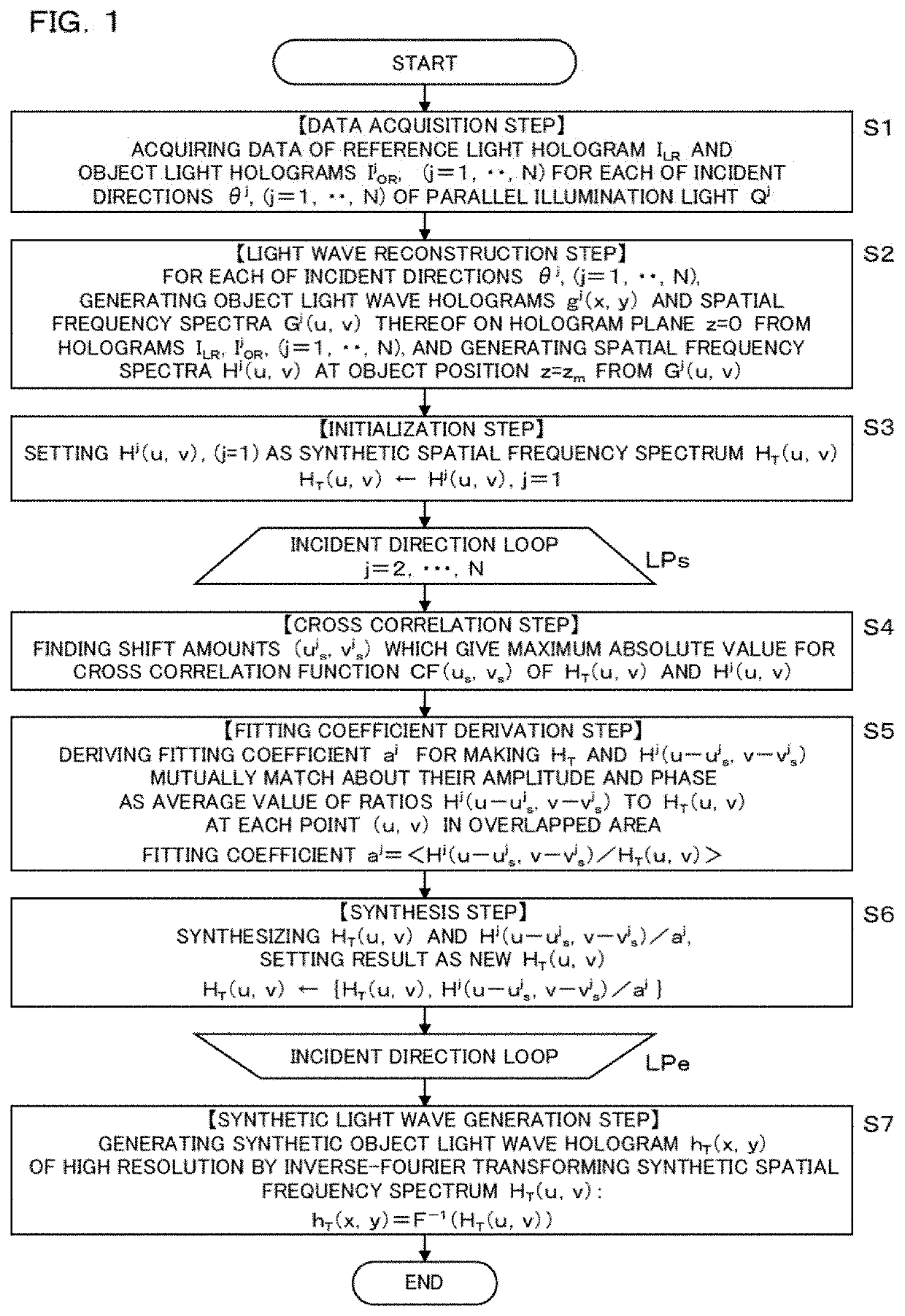
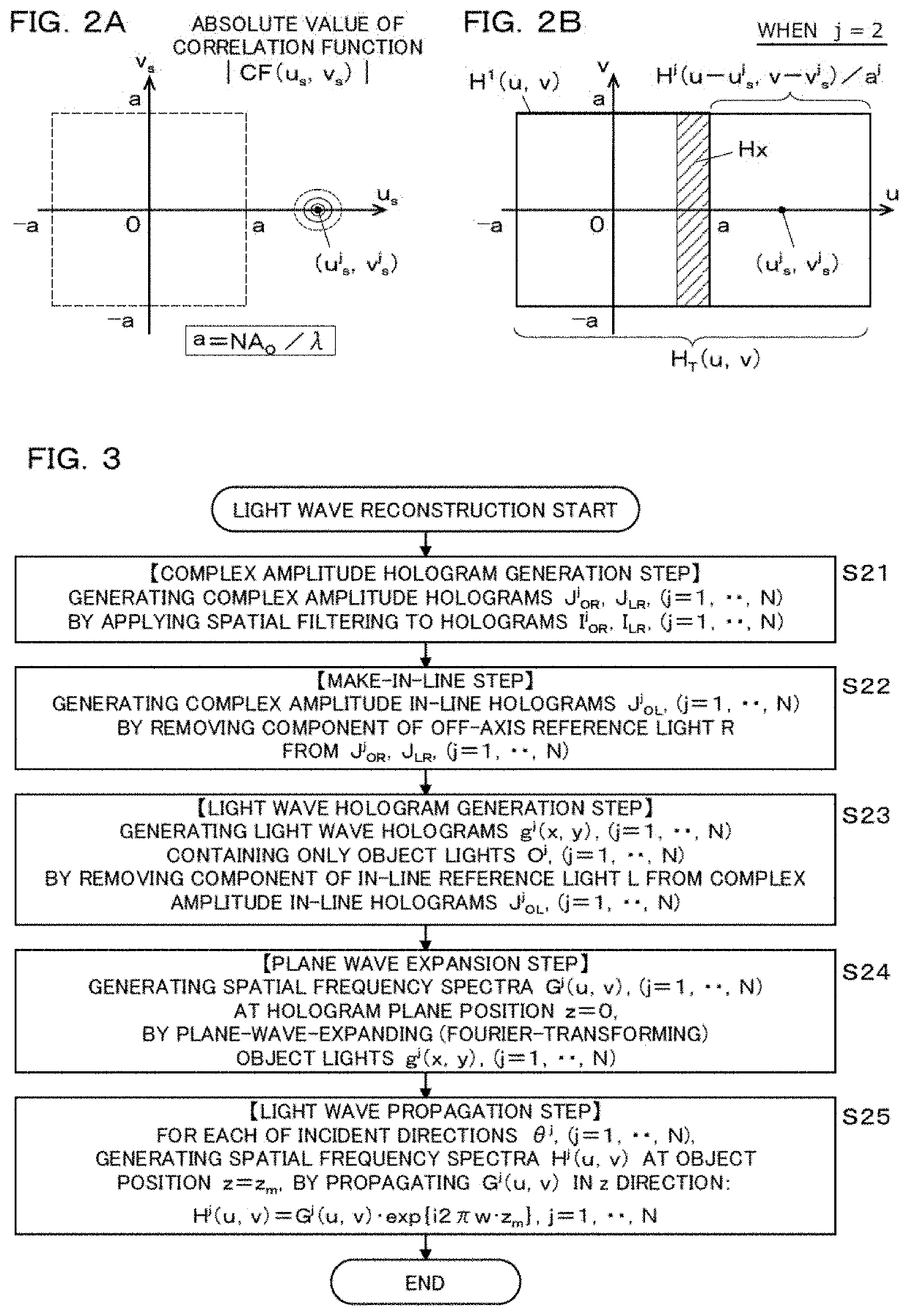
[0078]FIG. 1 to FIG. 3 show the data processing method according to the 1st embodiment. As shown in FIG. 1, this data processing method comprises a data acquisition step (S1), a light wave reconstruction step (S2), an initialization step (S3), three steps in an incident direction loop LPs and LPe, namely, a mutual cross correlation step (S4), a fitting coefficient derivation step (S5), a synthesis step (S6), and a step after the loop, namely, a synthetic light wave generation step (S7).

[0079]The present data processing method performs synthesis of hologram data using a principle that: when an object is illuminated with an obliquely incident parallel illumination light Q and an object light O emitted from the object is recorded as an object light off-axis hologram IOR using a reference light R, a spatial frequency spectrum H(u, v) of the object light O derived from the hologram IOR shifts in a spatial frequency space (u, v) according to an incident angle θ ...

tenth embodiment

[0180]With reference to FIG. 22 to FIG. 24, the light wave hologram g and the spatial sampling interval δ are described. Each of the holographic imaging devices described above records the object light O by using the spherical wave reference light R having the focal point P1 at a position close to the generation point of the object light O spreading like a spherical wave. Therefore, the spatial frequency band of the hologram of the interference fringes of the object light O and the reference light R is narrowed. From such a hologram, if a hologram with only the object light O alone is taken out, the spatial frequency band becomes broader to high frequency. From this, it can be seen that the light wave hologram g(x, y) of above equation (10) expressing the wavefront of the object light O has a broader space frequency band than the complex amplitude in-line hologram JOL(X, y) of above equation (9).

[0181]The spatial variation of the light wave hologram g(x, y) becomes larger as going a...

example 1

tion of Long Working Distance, Wide Field of View, Transmission Type Imaging Device

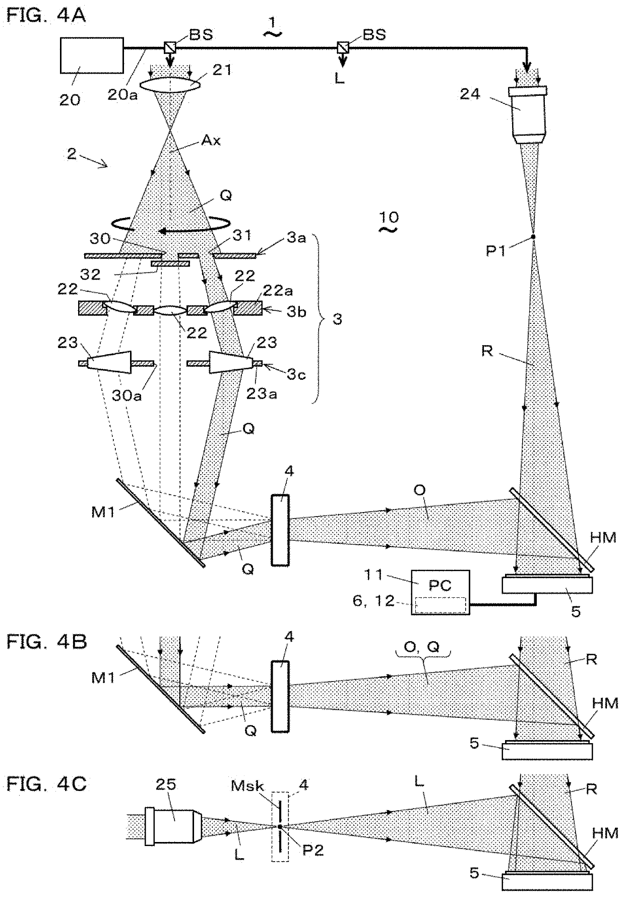
[0206]Using the holographic imaging device, which has the angle change unit 3 shown in the 6th embodiment (FIG. 11), imaging tests were performed with a USAF test target as a subject (object 4). A green excitation solid-state laser (wavelength: 532 nm, output: 50 mW) was used as a light source, and an off-axis spherical wave reference light R was generated using an objective lens with a numerical aperture of 0.28. A monochrome camera link CCD camera was used as the photo-detector 5. The distance from the CCD to the target, the numerical aperture, and the recordable field size W are, respectively, zm=52.4 cm, NAO=0.019, and W=25 mm. The theoretical resolution is 14.0 μm, which is determined from the numerical aperture NAO=0.019.

[0207]The configuration of the optical system of a holographic imaging device having a numerical aperture NAO=0.019 can be regarded as a configuration in which the numerical ape...


PUM


Abstract

A holographic imaging device and method realizes both a transmission type and a reflection type, and also realizes a long working distance wide field of view or ultra-high resolution. Object light emitted from an object, sequentially illuminated with parallel illumination light whose incident direction is changed, is recorded on a plurality of object light holograms for each incident direction using off-axis spherical wave reference light. The reference light is recorded on a reference light hologram using in-line spherical wave reference light being in-line with the object light. An object light wave hologram and its spatial frequency spectrum at the object position are generated for each incident direction using each hologram. A synthetic spectrum which occupies a wider frequency space is generated by matching each spectrum in the overlapping area, and a synthetic object light wave hologram with increased numerical aperture is obtained thereby.

Description

TECHNICAL FIELD[0001]The present invention relates to digital holography, and relates to a holographic imaging device for improving resolution and a data processing method used for the device.BACKGROUND ART[0002]Conventionally, there is a holography technique for analyzing light waves such as reflected light and transmitted light by recording on a recording medium, such as a photographic plate called hologram, together with light intensity and phase data. In holography in recent years, data of the intensity and phase of a light wave are acquired as digital data using a photo-detector and a semiconductor memory and the like, or a hologram itself is generated as digital data on a computer, so as to be analyzed. Such a holography is called a digital holography.[0003]In the digital holography, various techniques have been proposed for achieving high-speed and high-precision acquisition and processing of hologram data, and are applied to imaging. For example, a digital holography has bee...

Claims


Application Information

Patent Timeline
IPC IPC(8): G03H1/08G03H1/04G03H1/00G03H1/22
CPCG03H1/0465G03H1/0005G03H1/2202G03H2001/2239G03H2001/0413G03H2001/0473G03H2001/005G03H1/0808G03H1/0404G03H1/0866G03H2001/0415G03H2001/0825G03H2001/0445G03H2001/0456G02B21/06G02B21/12G02B21/18G03H1/0443G03H2001/0447G03H2001/046G03H2001/045G03H2001/0469G03H2001/0471G03H2001/2655G03H2222/44G03H2227/03G03H1/26
Inventor SATO, KUNIHIRO
Owner UNIV OF HYOGO
Why Eureka
Try Eureka