Air metal battery having a rotating anode and a cathode assembly

Active Publication Date: 2020-12-10
ALUMAPOWER CORP
View PDF0 Cites 4 Cited by
  • Summary
  • Abstract
  • Description
  • Claims
  • Application Information

AI Technical Summary

Benefits of technology

The patent describes an air metal battery that uses an electrolyte fluid to produce a hydrostatic force at the cathode surface. The battery includes a cathode assembly with a fluid path for pumping the electrolyte fluid through the cathode assembly and out of the cathode surface. An anode is positioned proximate to the cathode assembly and rotates relative to it using a thrust bearing. A shaft is in contact with a sliding conductor that collects electrical charge. The anode remains spaced from the cathode surface during operation due to the hydrodynamic force of the electrolyte fluid. The patent also describes a battery assembly that includes multiple air metal batteries and an electrolyte fluid. Each air metal battery has a cathode assembly with a fluid path for pumping the electrolyte fluid through it and out of the cathode surface, thereby producing a hydrostatic force at the cathode surface. A shaft is in contact with a sliding conductor in each air metal battery, which collects electrical charge. The anode of each battery remains spaced from the corresponding cathode surface during operation due to the hydrodynamic force of the electrolyte fluid. The technical effects of the patent include an improved design for an air metal battery that produces a stable hydrostatic force at the cathode surface and a battery assembly that includes multiple air metal batteries.

Problems solved by technology

Metal air batteries are known to suffer from parasitic corrosion problems.
Corrosion of edges of anode plates and parasitic corrosion of the surface changes the shape and the I2R losses (electrical resistance) due to the changing distance between the anode and cathode due to this corrosion.
The metal anode of a metal air battery is consumed during operation and causes some issues with performance and reliability of the system.
A metal air battery that has a fixed anode cathode suffers from an increase in the resistance between the anode and cathode due to the corrosion of the metal anode surface away from the cathode.
Additionally, the edges of the metal anode that is not directly parallel to the cathode have parasitic corrosion that also can produce hydrogen gas in the right circumstances.
Some methods in protecting the edges of the metal anodes have been designed that are adequate in control of this issue but complicate the mechanical reload of metal anodes because perfect seal of the system is required due to the direct immersion of the anode in the electrolyte.
When the electrical circuit in a metal air battery is interrupted (e.g. turned off) the electrolyte reacts instantly with the metal to produce dangerous volumes of hydrogen gas that must be vented from the battery system.
The hydrogen bubbles collect in the electrolyte rapidly and increase the electrical resistance of the battery so that even if the battery is quickly turned back on full power is not available until the electrolyte with hydrogen bubbles is flushed from the system.
Attempts to drain the electrolyte out of a metal air battery does shut down the power output but has been found to result in small droplets and liquid film coatings of the metal anode that produce large amounts of hydrogen gas and corrode the metal unevenly producing pits and voids that reduce the efficiency and amount of power available from the system.
In summary it is very difficult to turn off a metal air battery and then turn it on again without damage to the complete system so they are left on for the lifetime of the anode.
However, these systems do not provide for inconsistency in the electric field between different areas of the anode cathode assembly.
Additionally, such systems cannot provide for complete removal of electrolyte from a previously operating system.

Method used


Image

  • Air metal battery having a rotating anode and a cathode assembly
  • Air metal battery having a rotating anode and a cathode assembly
  • Air metal battery having a rotating anode and a cathode assembly

Examples


Embodiment Construction

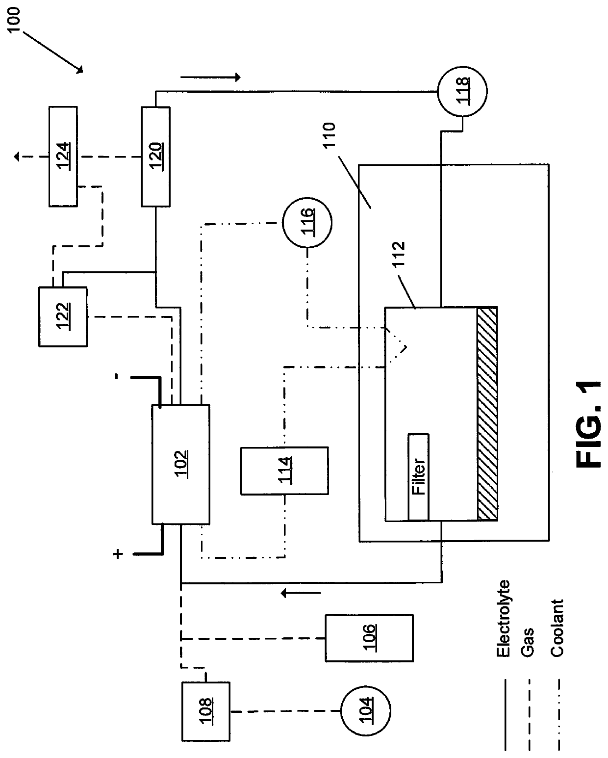
[0035]The present disclosure pertains to a metal air battery that provides for complete, rapid shutdown of power without parasitic corrosion and production of dangerous hydrogen gas as described above. This disclosure also provides for the rapid restart to full power and production of constant power output throughout the consumption of the metal anode. Some embodiments of the disclosed air battery provide for a low cost metal anode configuration that does not need high integrity edge seals and that can be automatically loaded into the metal air battery system for the purposes of extended operation.

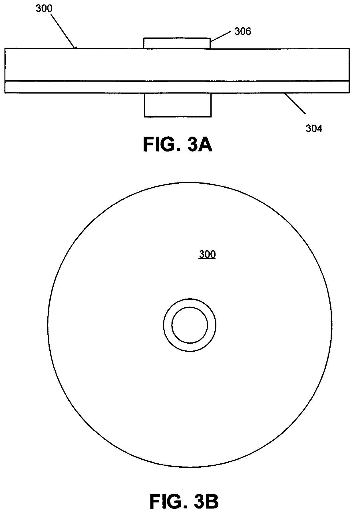
[0036]As shown in FIG. 3A and FIG. 3B, an anode disc 300 is shown configured to provide solutions to many conventional problems experienced by conventional air batteries. The anode disc 300 may be comprised of metal (e.g. aluminum) bonded to a plastic mounting bracket 304 of the same diameter as the anode disc 300. See FIG. 3A (side view) and FIG. 3B (top view). The plastic mounting bracke...


PUM


Abstract

A metal air battery system having a rotating anode / cathode assembly. The assembly is mounted in a housing system that provides a mechanism for loading of fresh metal anodes for the purpose of mechanical recharge of the battery. The anode and cathode are able to rotate at high speed for the purposes of producing local high centrifugal (g) forces on their respective surfaces for the purpose of wiping clean liquid electrolyte from their surface to provide for almost instantaneous shutdown of chemical reactions producing hydrogen gas and electric current. The anode and cathode are also rotated at slower speeds for the purpose of providing an even corrosion of the metal anode surface and the cathode rides on the liquid electrolyte using a dynamic and or static liquid bearing design. This liquid bearing provides a constant distance and therefore electrical resistance in the battery.

Description

CROSS-REFERENCE TO RELATED APPLICATIONS[0001]This application claims priority to and is a non-provisional of U.S. Patent Applications 62 / 567,963 (filed Oct. 4, 2017), 62 / 720,957 (filed Aug. 22, 2018) the entirety of which are incorporated herein by reference.BACKGROUND OF THE INVENTION[0002]The subject matter disclosed herein relates to metal air batteries. Metal air batteries provide high energy density power sources that show promising applications as mobile and stationary distributed power sources. They have the potential to replace the internal combustion engines found in hybrid cars and aircraft since the energy density, efficiency of conversion approach those of hydrocarbon fuels.[0003]FIG. 1 depicts a schematic representation of a conventional aluminum-oxygen cell system 100. The system 100 comprises an air metal battery 102, an air blower 104 or an oxygen supply 106 and a carbon dioxide scrubber 108. An electrolyte tank 110 with a filter 112 is also present. A coolant system...

Claims


Application Information

Patent Timeline
IPC IPC(8): H01M12/02H01M12/06H01M2/40H01M4/38H01M50/77
CPCH01M2/40H01M2004/027H01M4/38H01M12/06H01M12/02H01M2004/025H01M10/4214H01M12/065H01M50/77
Inventor SHEERIN, GEOFFREY T.
Owner ALUMAPOWER CORP
Why Eureka
Try Eureka