Method of forming topology-controlled amorphous carbon polymer film

a topology-controlled, carbon-based film technology, applied in the direction of vacuum evaporation coating, chemical vapor deposition coating, coating, etc., can solve the problems of increasing the difficulty of void-free filling of high aspect ratio spaces (e.g., ar3), difficult to control the thickness of the film depositing on the top surface,

Pending Publication Date: 2021-01-21
ASM IP HLDG BV
View PDF5 Cites 149 Cited by
  • Summary
  • Abstract
  • Description
  • Claims
  • Application Information

AI Technical Summary

Problems solved by technology

However, with miniaturization of wiring pitch of large scale integration (LSI) devices, void-free filling of high aspect ratio spaces (e.g., AR≥3) becomes increasingly difficult due to limitations of existing deposition processes.
However, if a certain application, where a sacrificial etch stop layer or protection layer, for example, is necessary only on the top surface of a recess, requires top-only deposition of amorphous carbon using the above gap-fill technology on a substrate without deposition in trenches, e.g., at the bottom of trenches, of the substrate, there might be the following issues: i) deposition by the gap-fill technology is essentially bottom-up deposition, and thus, a certain amount of film may inevitably be deposited at the bottom of the recess; ii) in the event that a recess is an ultradeep hole (having an aspect ratio of, e.g

Method used


Image

  • Method of forming topology-controlled amorphous carbon polymer film
  • Method of forming topology-controlled amorphous carbon polymer film
  • Method of forming topology-controlled amorphous carbon polymer film

Examples


reference example 1 (fig.4)

Reference Example 1 (FIG. 4)

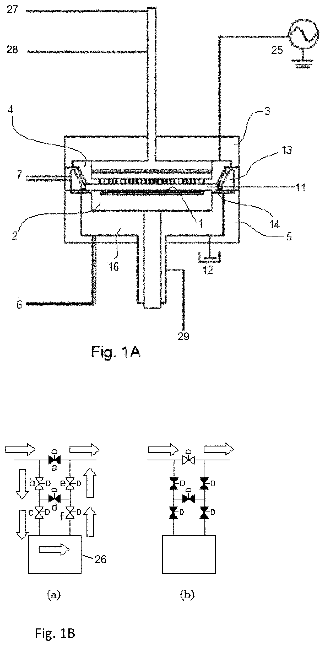
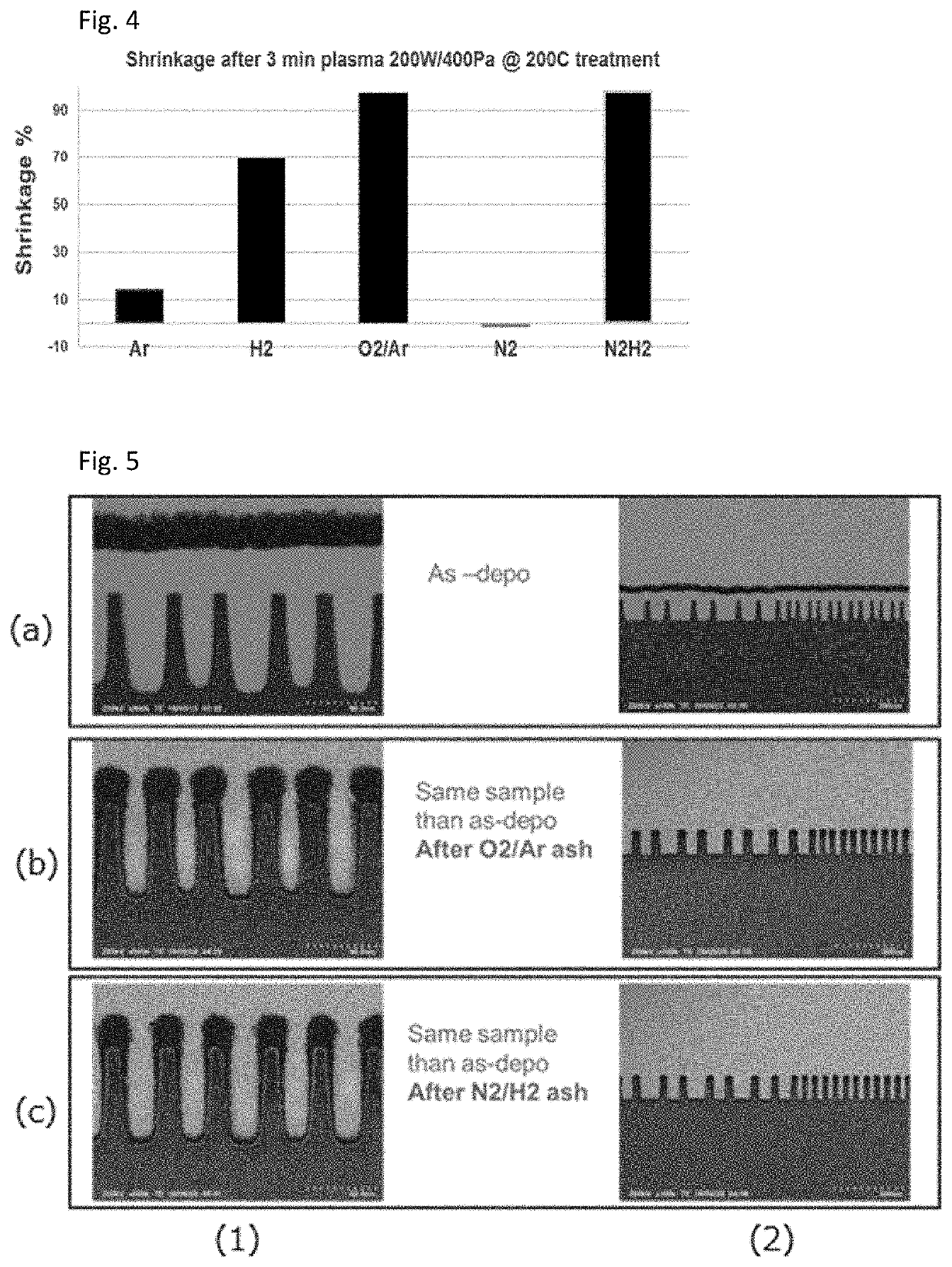
[0065]A flowable amorphous carbon polymer film (a-C blanket layer) was deposited using cyclopentene at a thickness of 100-150 nm on a Si substrate (having a diameter of 300 mm and a thickness of 0.7 mm) by PEALD-like process which is defined in U.S. patent application Ser. No. 16 / 026,711 and Ser. No. 16 / 427,288, following the deposition process illustrated in FIG. 10 under the conditions shown in Table 1 below using the apparatus illustrated in FIG. 1A and a gas supply system (FPS) illustrated in FIG. 1B. Post-deposition plasma treatment was conducted on the flowable amorphous carbon polymer film under the conditions shown in Table 1 below, which was conducted in the same reaction chamber as in the deposition process, in order to evaluate film shrinkage effect by each post-deposition treatment.

TABLE 1(numbers are approximate)DepoSUS temp (° C.).70SHD temp (° C.)75Wall temp (° C.)75BLT temp (° C.)RTPressure (Pa)1100Gap (mm)14Feed time (s)0.4Purge (s)0.1RF ...

reference example 2 (fig.5)

Reference Example 2 (FIG. 5)

[0074]A flowable amorphous carbon polymer film (a-C film) was deposited on a Si substrate (having a diameter of 300 mm and a thickness of 0.7 mm) having trenches with an opening of approximately 25 to 100 nm, which had a depth of approximately 85 nm (an aspect ratio was approximately 3.4 to 0.85), by PEALD-like process in a bottom-up manner in the same manner under the same conditions as those in Reference Example 1 except that the deposition continued until the trenches were fully filled and the top surface of the a-C film became planar. Thereafter, the post-deposition plasma treatment was conducted in the same manner under the same conditions as those using O2 / Ar and N2 / H2 in Reference Example 1 except that the plasma treatment continued until all the film was removed.

[0075]FIG. 5 shows STEM photographs of cross-sectional views of the trenches, wherein raw (a) represents the trenches subjected to full-fill deposition of the flowable film, raw (b) repres...

example 3 (table 2 , fig.9)

Example 3 (Table 2, FIG. 9)

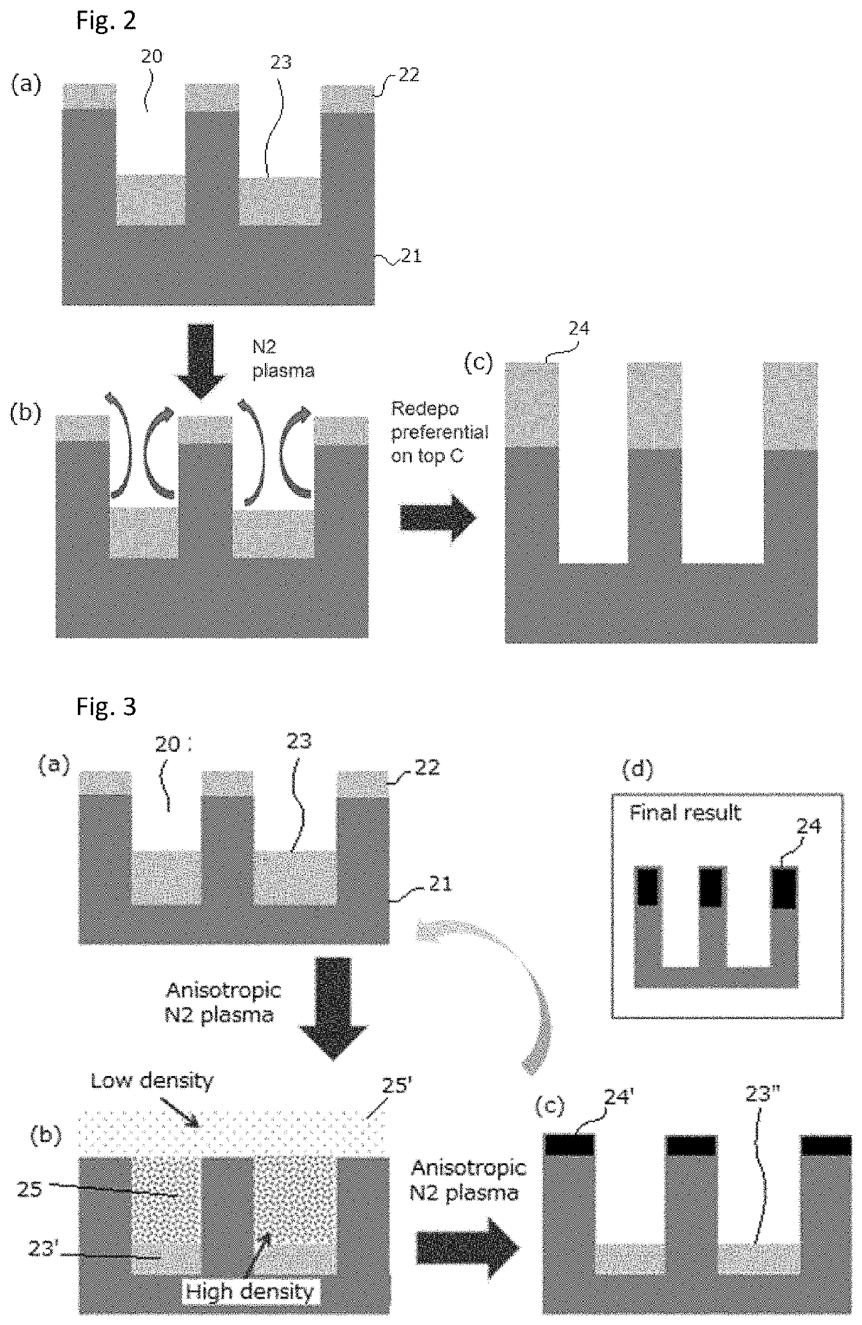
[0080]In Example 3, an amorphous carbon polymer film was formed in the same manner under the same conditions as in Example 1, and then, the nitrogen plasma treatment was conducted on the film in the same manner under the same conditions as in Example 1 to obtain a redeposited amorphous carbon polymer film on the top surface of the trenches. The properties of the resultant amorphous carbon polymer films were evaluated. The results are shown in Table 2 below and FIG. 9.

TABLE 2(numbers are approximate)STD-filmRedeposited film(No N2 (N2 plasmaplasma)treated)Deposition Rate [nm / min]122.5RI1.541.61Water Contact Angle [°] (25° C.)66.146.1Stress [MPa]~0−80RBS [%]C51.040.0H46.040.2O3.03.5NND16.3Thermal 50° C. / 30 min0—shrinkage [%]125° C. / 30 min10-20—200° C. / 30 min17.67.6300° C. / 30min35.423.9

[0081]As shown in Table 2, the thermal shrinkage of the amorphous carbon polymer film with the nitrogen plasma treatment (“Redeposited film”) was remarkably lower than that of t...


PUM

PropertyMeasurementUnit
Timeaaaaaaaaaa
Timeaaaaaaaaaa
Thicknessaaaaaaaaaa

Abstract

In exemplary embodiment, a method of top-selective deposition using a flowable carbon-based film on a substrate having a recess defined by a top surface, sidewall, and a bottom, includes steps of: (i) depositing a flowable carbon-based film in the recess of the substrate in a reaction space until a thickness of the flowable carbon-based film in the recess reaches a predetermined thickness, and then stopping the deposition step; and (ii) exposing the carbon-based film to a nitrogen plasma in an atmosphere substantially devoid of hydrogen and oxygen so as to redeposit a carbon-based film selectively on the top surface.

Description

CROSS-REFERENCE TO RELATED APPLICATIONS[0001]This application claims the benefit of U.S. Provisional Application No. 62 / 876,589, filed on Jul. 19, 2019, in the United States Patent and Trademark Office, the disclosure of which is incorporated herein in its entirety by reference.BACKGROUND OF THE INVENTIONField of the Invention[0002]The present invention generally relates to a method of forming a topology-controlled carbon-based film on a patterned recess of a substrate, particularly to a method of top-selective deposition using a flowable carbon-based film on the patterned recess.Description of the Related Art[0003]In processes of fabricating integrated circuits such as those for shallow trench isolation, inter-metal dielectric layers, passivation layers, etc., it is often necessary to fill trenches (any recess typically having an aspect ratio of one or higher) with insulating material. However, with miniaturization of wiring pitch of large scale integration (LSI) devices, void-free...

Claims


Application Information

Patent Timeline
IPC IPC(8): H01L21/02H01L21/762C23C16/52C23C16/455
CPCH01L21/02118H01L21/76224H01L21/02274C23C16/45536H01L21/0228C23C16/52H01L21/76825H01L21/02271H01L21/0234H01L21/56H01L21/02126C23C14/0605C23C14/0036C23C16/045C23C16/26C23C16/56C23C14/048C23C16/04C23C16/505C23C16/45523H01L21/02115
Inventor BLANQUART, TIMOTHEE JULIEN VINCENT
Owner ASM IP HLDG BV
Why Eureka
Try Eureka