Pulsatile Balloon Catheter Systems and Methods of Using the Same

a catheter system and catheter technology, applied in the field of catheter systems and catheter methods, can solve the problems of cp-burdened vessels, impaired vessel perfusion, major adverse cardiovascular events, and myocardial infarction, and achieve the effect of reducing the risks of ionizing radiation backscatter and shortening the career

Pending Publication Date: 2022-09-15
AMPLITUDE VASCULAR SYST INC
View PDF0 Cites 2 Cited by
  • Summary
  • Abstract
  • Description
  • Claims
  • Application Information

AI Technical Summary

Benefits of technology

[0007]In addition to the concern for patient outcomes, endovascular procedures and surgeries can significantly affect the treating physician. Over an interventional cardiologists' career, s / he can be exposed to an estimated 50 mSv-200 mSv of ionizing radiation, which is equivalent to 2,500-10,000 chest X-rays. With this amount of radiation exposure, treating physicians are exposed to serious long-term health issues such as cancer, cataracts, cognitive function, and reproductive effects. To mitigate the risks of ionizing radiation backscatter, physicians wear personal protective equipment (PPE) (e.g., heavy lead suits) for protection. Because of this PPE, a statistically significant group of interventional cardiologists reported musculoskeletal injuries that may have the effect of shortening careers.

Problems solved by technology

The plaque buildup from atherosclerosis limits blood flow through these arteries and can lead to major adverse cardiovascular events such as myocardial infarction, limb amputation, and mortality.
CP-burdened vessels have reduced vascular elasticity and impaired vessel perfusion.
Because of this reduced compliance and perfusion, CPs are associated with an increased risk of mortality and other adverse events.
However, CP-burdened vessels pose special challenges for effective intravascular treatments.
However, because of the strength of CP, full balloon expansion is often restricted, and the CP remains unfractured.
Without sufficient balloon expansion and CP fracture, the vessel remains with a residual stenosis limiting downstream blood flow indicating a poor outcome, a high risk of immediate or long-term failure, and the need for additional procedures.
In some scenarios, the entire artery is diseased, and the balloon remains uniformly unexpanded and does not achieve a full diameter.
These aggressive procedures subject patients to increased risks such as balloon rupture in 21% of cases, vessel dissection in 76% of cases and restenosis (i.e., post-procedure vessel re-narrowing) in 20-30% of cases.
During balloon pressurization, the metallic blades or cage can become embedded in soft-tissue or CP causing major procedural issues.
Poor outcomes have been associated with these balloons including restenosis in 20-30% of cases and major adverse events such as vessel perforation, myocardial infarction, or death in 6% of cases.
Short-term efficacy and safety with lithotripsy devices have been demonstrated through clinical trials; however, recent case reports have shown that these >50 ATM cavitation explosions lead to dangerous arterial dissections and perforations.
However, atherectomy is more challenging technically and grinds CP and surrounding healthy tissue, which can lead to long-term vessel injury.
In addition to the concern for patient outcomes, endovascular procedures and surgeries can significantly affect the treating physician.
With this amount of radiation exposure, treating physicians are exposed to serious long-term health issues such as cancer, cataracts, cognitive function, and reproductive effects.

Method used


Image

  • Pulsatile Balloon Catheter Systems and Methods of Using the Same
  • Pulsatile Balloon Catheter Systems and Methods of Using the Same
  • Pulsatile Balloon Catheter Systems and Methods of Using the Same

Examples


specific embodiment

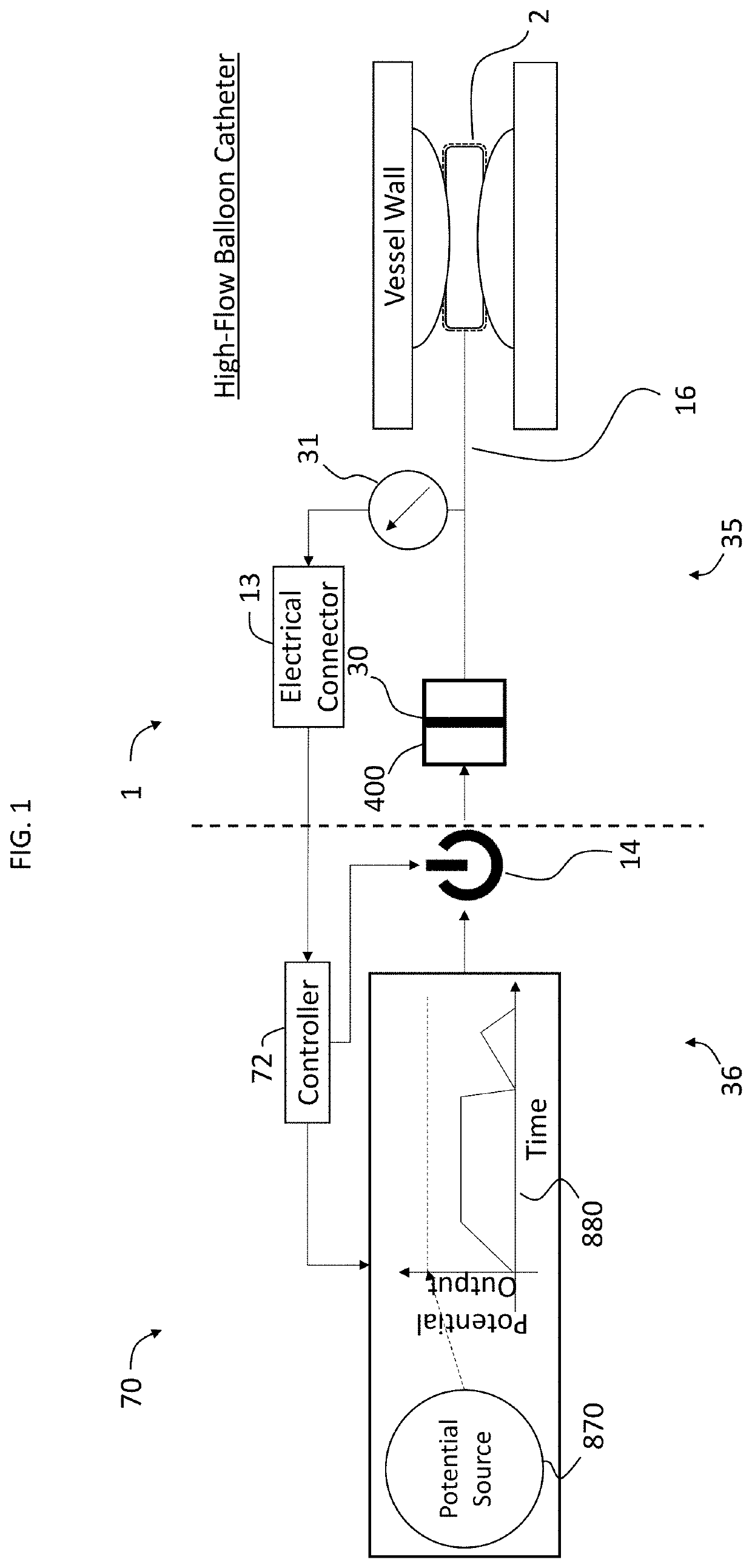
[0073]A system in accordance with embodiment of the invention for generating high frequency angioplasty balloon oscillations is schematically illustrated in FIG. 1. In some instances, the system can include a pulse generator which has a potential energy source, such as a high voltage or pressure source, a switching system, e.g., for controlling the high potential source, etc., and a balloon catheter assembly for converting the output of the pulse generator (i.e., first pulsatile energy), into hydraulic oscillations (i.e., second pulsatile energy) of an angioplasty balloon. In embodiments, the potential energy source acts to drive the balloon angioplasty oscillations, a switching system controls the frequency, duty cycle, and / or amplitude of the outputted energy from the pulse generator, a proximal connector of the balloon catheter assembly converts the outputted energy into hydraulic oscillations that thereby generate oscillations in an angioplasty balloon catheter, and the high flo...

examples

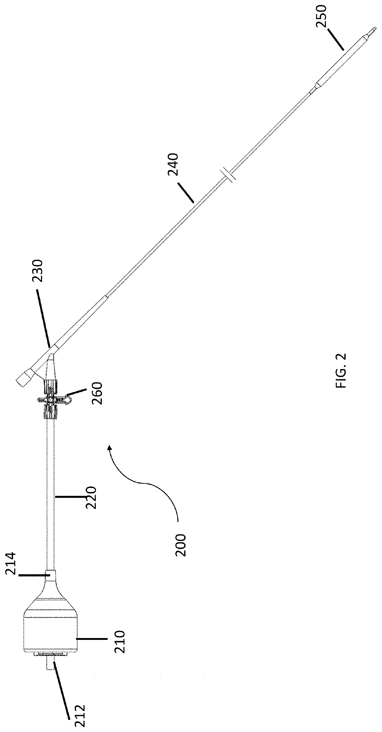
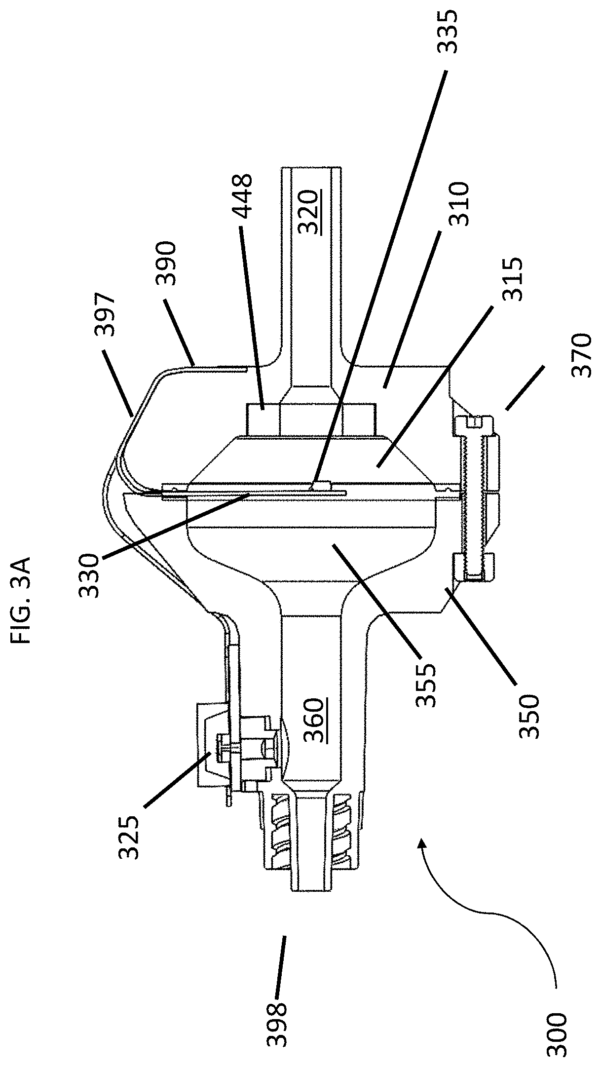
[0149]FIG. 18 provides a picture of a balloon catheter assembly according to an embodiment of the invention. FIG. 19 shows the assembly process for the proximal connector of the balloon catheter assembly shown in FIG. 18. The first step of the assembly process is to fix the electronic flexible printed circuit board assembly to the diaphragm and pressure sensor. For example, epoxy and solder, respectively, may be used. The pressure sensor and diaphragm may be fixed to the distal flange. Using an appropriate fixation technique (e.g., fasteners, welding, etc.), the proximal flange may be fixed to the distal flange. The electronic connector may be fixed to the front face of the proximal flange with epoxy, for example, so as to provide a reliable connection to the hand-held actuator. FIG. 6 represents testing performed on the described embodiment and physical assembly. The pressure is shown to increase while the force at the distal balloon increases as well. The force produced during osc...


PUM


Abstract

Pulsatile balloon catheter systems are provided. Aspects of the systems include: a pulse generator; and a balloon catheter assembly operably connected to the pulse generator. In embodiments, the balloon catheter assembly includes: a proximal connector operably connecting the balloon catheter assembly to the pulse generator and configured to transduce a first pulse energy generated by the pulse generator to a second pulse energy; a distal balloon; and a catheter component, where the catheter component includes a fluidic passage operably positioned between the proximal connector and the distal balloon, which passage is configured to propagate the second pulse energy from the proximal connector along the fluid passage to the distal balloon. Also provided are balloon catheter assemblies and kits that include the same. Also provided are systems and methods for assessing vessel compliance in-vivo. Also provided are systems and methods for determining system state of balloon catheter systems. The systems, assemblies and kits find use in a variety of different applications, including balloon angioplasty applications.

Description

CROSS-REFERENCE TO RELATED APPLICATIONS[0001]This application is a continuation-in-part of International Application No. PCT / US2022 / 014785 filed Feb. 1, 2022, which claims priority to the filing dates of: U.S. provisional patent application Ser. No. 63 / 274,832 filed Nov. 2, 2021; U.S. provisional patent application Ser. No. 63 / 241,295 filed Sep. 7, 2021; and U.S. provisional patent application Ser. No. 63 / 145,641 filed Feb. 4, 2021; the disclosures of which applications are incorporated herein by reference in their entirety.INTRODUCTION[0002]This section provides background information related to the present disclosure which is not necessarily prior art. This section also provides a general summary of the disclosure and is not a comprehensive disclosure of its full scope or all of its features.[0003]Ischemic heart disease, the number one cause of death in the world, is caused by atherosclerotic plaque build-up within human vasculature. Worldwide, these diseases represent 84.5% of ca...

Claims


Application Information

Patent Timeline
Patent Type & Authority Applications(United States)
IPC IPC(8): A61B17/22A61M5/00
CPCA61B17/22012A61M5/007A61B2090/064A61M25/10184A61M25/104A61M2025/0002A61B2090/063A61B2017/00022A61B2017/00039A61B2017/00477A61B2017/00964A61B2017/22001A61B2017/22038A61B2017/22054A61B2017/22062
Inventor CHISENA, ROBERTGURM, HITINDER
Owner AMPLITUDE VASCULAR SYST INC
Why Eureka
Try Eureka