Eureka AIR delivers breakthrough ideas for toughest innovation challenges, trusted by R&D personnel around the world.

Methods and systems for cathode pre-lithiation layer

Pending Publication Date: 2022-11-10
A123 SYSTEMS LLC
View PDF0 Cites 0 Cited by
  • Summary
  • Abstract
  • Description
  • Claims
  • Application Information

AI Technical Summary

Benefits of technology

The patent text describes a method for improving the performance and energy density of lithium-ion batteries by applying a pre-lithiation layer to the cathode prior to first charge / discharge. This pre-lithiation layer can be applied using a slurry-based process and can include a sacrificial pre-lithiation reagent that provides extra Li+ ions to the cathode. By doing this, the pre-lithiation layer can increase the capacity and initial energy density of the battery. The method also includes optimizing the processing parameters to improve the mechanical integrity and reduce interfacial impedance between the pre-lithiation layer and the cathode substrate. The pre-lithiation slurry can be formed by mixing and milling the cathode pre-lithiation reagent in a solvent for a sufficient duration to ensure uniform dispersion. The cathode pre-lithiation reagent can be pre-milled in an inert environment to reduce moisture exposure and the resulting battery may have a high porosity cathode active material layer with improved mechanical stability and reduced interfacial impedance.

Problems solved by technology

The SEI layer may prove detrimental to electrochemical performance as the formation process may result in non-negligible Li+ consumption (particularly in silicon-based anodes).
As such, SEI formation may lower the first-cycle coulombic efficiency (FCE), resulting in lower capacity and lower initial energy density, and thus poor cycling performance, of the lithium-ion battery.
However, direct inclusion of cathode pre-lithiation reagents into cathode active material layer slurries may be plagued with other issues.
As an example, some cathode pre-lithiation reagents may be relatively sensitive to moisture, potentially leading to degradation of such cathode pre-lithiation reagents prior to desired battery operation voltage windows (e.g., when Li+ may be provided to the anode).
As another example, some cathode pre-lithiation reagents may be incompatible with common binders [e.g., polyvinylidene fluoride (PVDF)], resulting in slurry gelation and thereby unprocessable slurries or relatively poor quality cathode coatings (e.g., having low adhesion).
As yet another example, some cathode pre-lithiation reagents may be incompatible with common slurry solvents [e.g., N-methyl-2-pyrrolidone (NMP)], making retention and dispersion of such cathode pre-lithiation reagents within such slurry solvents difficult.
Further, by layering the slurry-based coating on a preformed cathode substrate (e.g., a cathode active material layer disposed on a cathode current collector), additional interfacial interactions may present obstacles to high quality lamination and ionic and electronic conductivity.
Improper coating in this way may also result in undesirably low discharge capacity, which may be caused by increases in impedance ascribed to an additional cathode pre-lithiation layer having an improper design (e.g., high thickness, less effective coating process, etc.) or formulation (e.g., incompatible composition, etc.).
Moreover, such interfacial impedance between the cathode pre-lithiation layer and the cathode substrate (in addition to impedance within the cathode pre-lithiation layer) may compromise an overall cycle life and power performance of the lithium-ion battery.
Other issues ascribable to improper coating may include delamination or pulverization (e.g., loss of mechanical integrity) of the cathode pre-lithiation later from the cathode substrate, which may obstruct pores in the cathode substrate or a separator included in the lithium-ion battery and concomitantly obstruct Li-ion pathways, potentially leading to compromised electrochemical performance due to impedance increases or uncyclable cells due to internal shortages therein.
However, certain cathode pre-lithiation reagents may decompose absent the cathode catalyst.

Method used


Image

  • Methods and systems for cathode pre-lithiation layer
  • Methods and systems for cathode pre-lithiation layer
  • Methods and systems for cathode pre-lithiation layer

Examples


Embodiment Construction

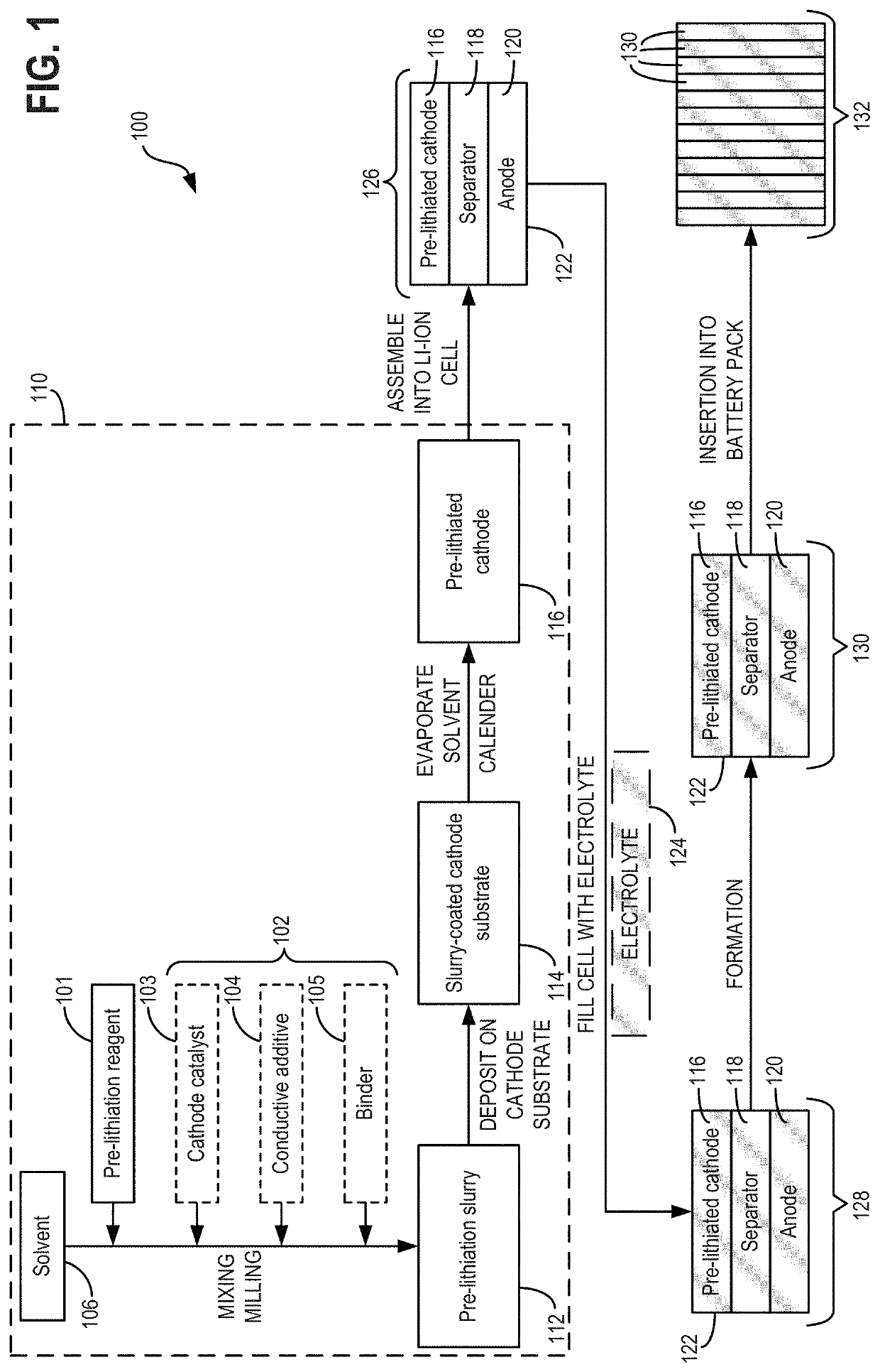
[0025]The following description relates to methods and systems for forming cathode pre-lithiation layers and slurries therefor. As described herein with reference to FIG. 1, the cathode pre-lithiation layer may be applied to a cathode substrate to form a pre-lithiated cathode for a lithium-ion secondary battery (referred to herein as a “lithium-ion battery”). The cathode pre-lithiation layer may be formed by casting, drying, and calendering a slurry on the cathode substrate, the slurry including a nanoscale pre-lithiation reagent uniformly dispersed throughout. The uniform dispersion of the nanoscale pre-lithiation reagent in combination with the relatively small physical dimensions thereof may result in an increased mechanical integrity of the finally-formed cathode pre-lithiation layer, as well as facilitating slurry processing and increasing an overall slurry quality. Further, in some examples, the slurry may further include one or more additives, such as a cathode catalyst, a bi...


PUM


Abstract

Methods and systems are provided for forming a cathode pre-lithiation layer for a lithium-ion battery. In one example, a slurry for forming the cathode pre-lithiation layer may include a solvent including a uniform dispersion of a nanoscale cathode pre-lithiation reagent. The slurry may be cast onto a porous cathode active material layer and dried and calendered to form the cathode pre-lithiation layer. In some examples, the slurry may have a viscosity of up to 5000 cP at a shear rate of 100 s−1. In this way, delamination and interfacial impedance between the cathode pre-lithiation layer and the porous cathode active material layer may be reduced relative to a higher viscosity cathode pre-lithiation layer having a larger scale cathode pre-lithiation reagent cast onto a non-porous or low-porosity cathode active material layer.

Description

CROSS-REFERENCE TO RELATED APPLICATIONS[0001]The present application claims priority to U.S. Provisional Application No. 63 / 185,297, entitled “METHODS AND SYSTEM FOR CATHODE PRE-LITHIATION LAYER”, and filed on May 6, 2021. The entire contents of the above-listed application are hereby incorporated by reference for all purposes.FIELD[0002]The present description relates generally to methods and systems for a slurry-based cathode pre-lithiation layer, particularly for a lithium-ion battery.BACKGROUND AND SUMMARY[0003]Lithium-ion secondary batteries, or lithium-ion batteries, are widely used in a broad range of applications, including consumer electronics, uninterruptible power supplies, transportation, stationary applications, etc. A lithium-ion battery functions by passing Li+ ions from a positive electrode, or cathode, including positive electrode active materials (for example, lithium insertion / deinsertion materials) to a negative electrode, or anode, during battery charging and th...

Claims


Application Information

Patent Timeline
IPC IPC(8): H01M4/36H01M10/0525H01M10/04H01M4/04H01M4/62
CPCH01M4/366H01M10/0525H01M10/0468H01M4/0435H01M4/0471H01M4/0404H01M4/625H01M2004/021Y02E60/10H01M4/139H01M2004/028H01M4/13
Inventor ZHANG, LINGHONGCHEN, XIAORUIHU, SHAOCHENGWANG, XIQINGWANG, JUNYU, TAEHWANGIONET, PAUL
Owner A123 SYSTEMS LLC
Why Eureka
Eureka Blog
Learn More