Anisotropic conductive adhesive and method for preparation thereof and an electronic apparatus using said adhesive

a technology of anisotropic conductive adhesive and anisotropic conductive adhesive, which is applied in the direction of electrical apparatus casings/cabinets/drawers, non-metal conductors, instruments, etc., can solve the problems of inability to apply devices, inability to achieve fine-circuit short-circuit, and inability to meet the requirements of the device, etc., to achieve excellent bonding properties, easy manufacturing of image display modules, and good bonding reliability

Inactive Publication Date: 2000-03-21
SUMITOMO BAKELITE CO LTD
View PDF3 Cites 130 Cited by
  • Summary
  • Abstract
  • Description
  • Claims
  • Application Information

AI Technical Summary

Benefits of technology

The thermosetting resin type anisotropic conductive adhesive of the present invention provides excellent bonding properties, bonding reliability, storage stability and repair properties. Curing temperature and curing time of the anisotropic conductive adhesive of the present invention are low and short, respectively.
When the anisotropic conductive adhesive is used to bond electronic and electric parts for a semiconductor element, a semiconductor device, a printed circuit board, a liquid crystal display (LCD) panel, a plasma display panel (PDP), an electroluminescence (EL) panel, a field emission display (FED) panel, a tape carrier package and the like, it is possible to miniaturize, lighten the weight and facilitate manufacturing of an image display module (LCD, PDP, EL, FED), a computer, television, a measuring instrument and apparatus, a communication device and the like as well as to improve ease of handling of repairs.
Materials used in the examples and comparative examples are shown in Table 1.

Problems solved by technology

The reason why an anisotropic conductive adhesive has been commonly used to connect materials as explained above is because conventional methods, for example, soldering and the like, cannot be applied to the devices.
Materials for the devices explained above are normally not heat resistant and if the conventional methods are applied to the devices there is a risk of a short-circuit between adjacent terminals in the fine circuits.
However, the thermoplastic resin type is not practically acceptable since it cannot give satisfactory results in a long term environmental test because of insufficiency of bonding reliability caused by low water-vapor resistance and chemical resistance.
It is difficult to cure within a practical cure time at a temperature of less than 150.degree. C.
If the adhesive has improved storage stability, however, it takes a longer time or a high temperature to cure.
On the other hand, if the adhesive can cure in a shorter time at a low temperature, it does not have a good storage property.
Both are unsatisfactory.
Although when a thermoplastic resin type anisotropic conductive adhesive is used, it is not difficult to repair defects after bonding because the resin, which is not cured, is easy to dissolve with a solvent, it is difficult to debond fine circuits after they have been bonded with a thermoset resin type anisotropic conductive adhesive to correct defects, for example, misalignment, without breakage or damage of the bonded parts.
Such requirement conflicts with the properties of the thermoset resin type adhesive, i.e., high-adhesive properties and good bonding reliability.
None of the conventional thermoset resin type adhesives can satisfy this requirement.
When LCD and TCP are bonded, misalignment in the bonding pattern occurs because of stretching of TCP, or internal components of LCD are damaged by high bonding temperature because a bonding portion is very narrow.
Therefore, breaking of TCP wiring occurs.
Although it is possible to bond by a conventional thermoplastic resin type anisotropic conductive adhesive at a low temperature, bonding reliability is low because water vapor resistance and heat resistance of the resin are low.
This is not practical.
However, these proposals are not satisfactory for practical application because of problems, for example, insufficient storage stability of the adhesive resin, corrosion of bonded circuit terminals and the like.
However, an adhesive resin, which has well-balanced properties, i.e., curing characteristics, processability, adhesive properties at high temperature and high humidity, bonding reliability, storage properties and the like, has not been obtained.

Method used


Image

  • Anisotropic conductive adhesive and method for preparation thereof and an electronic apparatus using said adhesive

Examples


example 1

200 Parts by weight of a 50% solution of methacryloyl phenolic novolac resin represented by formula (4) dissolved in methyl ethyl ketone, 350 parts by weight of a 20% solution of diaminodiphenylmethane type bismaleimide represented by formula (7) dissolved in tetrahydrofuran, 5 parts by weight of 1,1,3,3- tetramethylbutylperoxyhexanoate, 500 parts by weight of a 20% solution of acrylonitrile-butadiene-methacrylic acid copolymer dissolved in methyl ethyl ketone, 5 parts by weight of caprolactam modified (meth)acryloyl hydroxyethyl acid phosphate and 7 parts by weight of Ni / Au metallized polystyrene particles were mixed and were evenly dispersed. The mixture was cast on polyethyleneterephthalate film treated with a mold parting agent to a thickness of 45 .mu.m after drying. After drying, the product was cut to a width of 2 mm to obtain an anisotropic conductive adhesive.

examples 2

Anisotropic conductive adhesives were prepared in the same manner as Example 1 except that materials and amounts of materials shown in Tables 2 and 3 were used.

TABLE 3

Evaluation

1. Preparation of a Test Sample

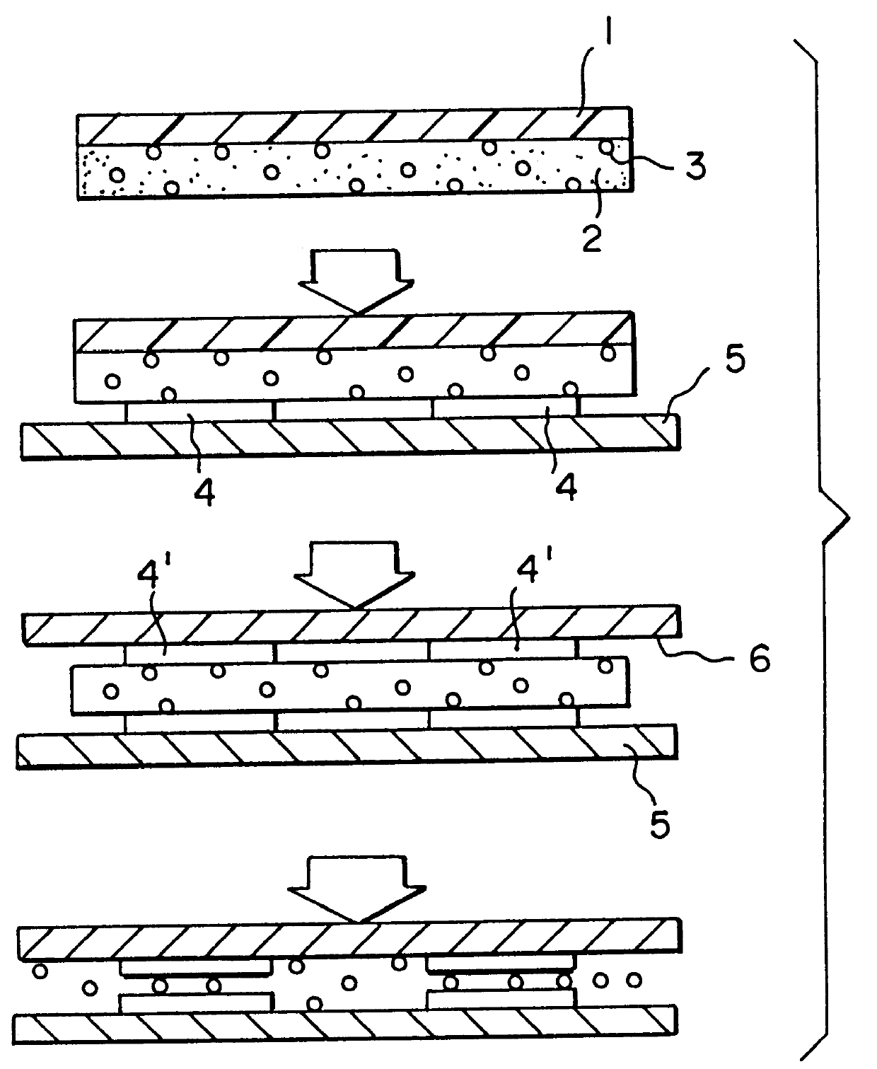
TCP (6) connected with circuit electrodes (4) having pitch of 0.3 mm and number of terminals of 60 which comprises a tin-plated (thickness of tin: 0.5 .mu.m) copper foil (thickness of 25 .mu.m) and polyimide (thickness of 75 .mu.m), and PCB (5) (thickness of 0.8 mm) connected with gold-flashing plated circuit electrodes (4') having pitch of 0.3 mm and number of terminals of 60, the PCB comprsing four layer boards (FR-4) of which outer and inner layers were copper films (thicknesss of 18 .mu.m), were pressed to bond with an anisotropic conductive adhesive (2). In FIG. 11 represents a carrier film for the adhesive (2) and 3 represents conductive particles in the adhesive.

2. Test Method of Bond Strength

The sample was pressed to bond at a temperature of 130.degree. C. and a pressure...

example 19

4 Parts by weight of caprolactam modified (meth)acryloyl hydroxyethyl acid phosphate, 1 part by weight of .beta.-(3,4- epoxycyclohexyl)ethyl trimethoxy silane and 100 parts by weight of methyl ethyl ketone were preliminarily reacted at a temperature of 40.degree. C. for one hour. 100 Parts by weight of urethane acrylate resin represented by formula (5), 60 parts by weight of a 50% solution of methacryloyl phenolic novolak resin (n / m+n=0.7 / 1, m+n=8) represented by formula (4) dissolved in methyl ethyl ketone, 3 parts by weight of 1,1,3,3- tetramethylbutylperoxy hexanoate, 300 parts by weight of a 20% solution of acrylonitrile-butadiene-methacrylic acid copolymer represented by formula (9) dissolved in methyl ethyl ketone and 4 parts by weight of Ni / Au metallized polystyrene particles were added and were dispersed evenly. The mixture was cast on polyethylenterephthalate film treated with a mold parting agent to a thickness of 35 .mu.m after drying. After drying, the product was cut to...


PUM

PropertyMeasurementUnit
temperatureaaaaaaaaaa
reaction temperatureaaaaaaaaaa

Abstract

An anisotropic conductive adhesive contains conductive particles dispersed in a resin composition, wherein the resin composition includes a radical polymerization resin (A), an organic peroxide (B), a thermoplastic elastomer (C) and a phosphoric ester (D). The resin composition can further contain an epoxy silane coupling agent (E) represented by formula (2) or (3). The resin composition is mixed with other components after the radical polymerization resin (A), the thermoplastic elastomer (C), the phosphoric ester (D) and the epoxy silane coupling agent (E) are reacted. It is also possible to preliminarily react only the phosphoric ester (D) and the epoxy silane coupling agent (E) and to react the product of the preliminary reaction with the radical polymerization resin (A) and the thermoplastic elastomer (C), and then to add other components. The anisotropic conductive adhesive of the present invention can be used for electrical joining of electronic or electric parts of electrical apparatus.

Description

The present invention relates to an anisotropic conductive adhesive that is used for joining minute circuits, e.g., a liquid crystal display (LCD) and a tape carrier package (TCP), TCP and a printed circuit board (PCB), and the like, a method for preparing the adhesive and an electronic apparatus in which the adhesive is used for the manufacture thereof.Recently there has been a dramatic increase in the need to join fine circuits, for example, a liquid crystal display (LCD) and a tape carrier package (TCP), TCP and a printed circuit board (PCB), and the like. An anisotropic conductive adhesive in which conductive particles are dispersed in a resin is used for such purposes. The anisotropic conductive adhesive is placed between parts which are to be connected to each other, and is heated and is pressed. Adjacent terminals in a direction parallel to the substrate surface are still insulated, but adjacent terminals in a direction perpendicular to the substrate surface are conductive. T...

Claims


Application Information

Patent Timeline
Patent Type & Authority Patents(United States)
IPC IPC(8): C09J9/02C09J9/00H01B1/20H01B1/24H01B1/22H05K3/32
CPCC09J9/02H01B1/20H01B1/22H01B1/24H05K3/323H05K2201/0129H05K2201/0133H05K2201/0239C09J201/00C09J11/06G02F1/13C09J2203/326C09J2203/318
Inventor MIYAMOTO, TETSUYAKAWATA, MASAKAZU
Owner SUMITOMO BAKELITE CO LTD
Why Eureka
Try Eureka