High frequency rotary pressure swing adsorption apparatus

a rotary pressure swing and adsorption technology, which is applied in the direction of chemistry apparatus and processes, separation processes, dispersed particle separation, etc., can solve the problems that the use of rotary displacement machines for tcpsa devices is not feasible, and achieves compact equipment, high frequency operation, and high energy efficiency.

Inactive Publication Date: 2000-05-02
AIR PROD & CHEM INC +1
View PDF25 Cites 186 Cited by
  • Summary
  • Abstract
  • Description
  • Claims
  • Application Information

AI Technical Summary

Benefits of technology

The present invention is intended to enable high frequency operation of pressure swing and vacuum swing adsorption processes, with high energy efficiency and with compact equipment of low capital cost. The invention applies most advantageously to relatively low pressure processes conducted near atmospheric pressure, so that fluid sealing may be accomplished primarily by narrow clearances between rotary positive displacement fluid machine components and their housings.

Problems solved by technology

Since rotary displacement machines (compared to reciprocating piston machines) are relatively impracticable at low shaft speed because of volumetric inefficiency due to leakage through clearances or alternatively because of excessive dry friction, the use of rotary displacement machines for TCPSA devices would not be feasible unless operation at relatively high cycle frequency is also feasible.

Method used


Image

  • High frequency rotary pressure swing adsorption apparatus
  • High frequency rotary pressure swing adsorption apparatus
  • High frequency rotary pressure swing adsorption apparatus

Examples


embodiment 200

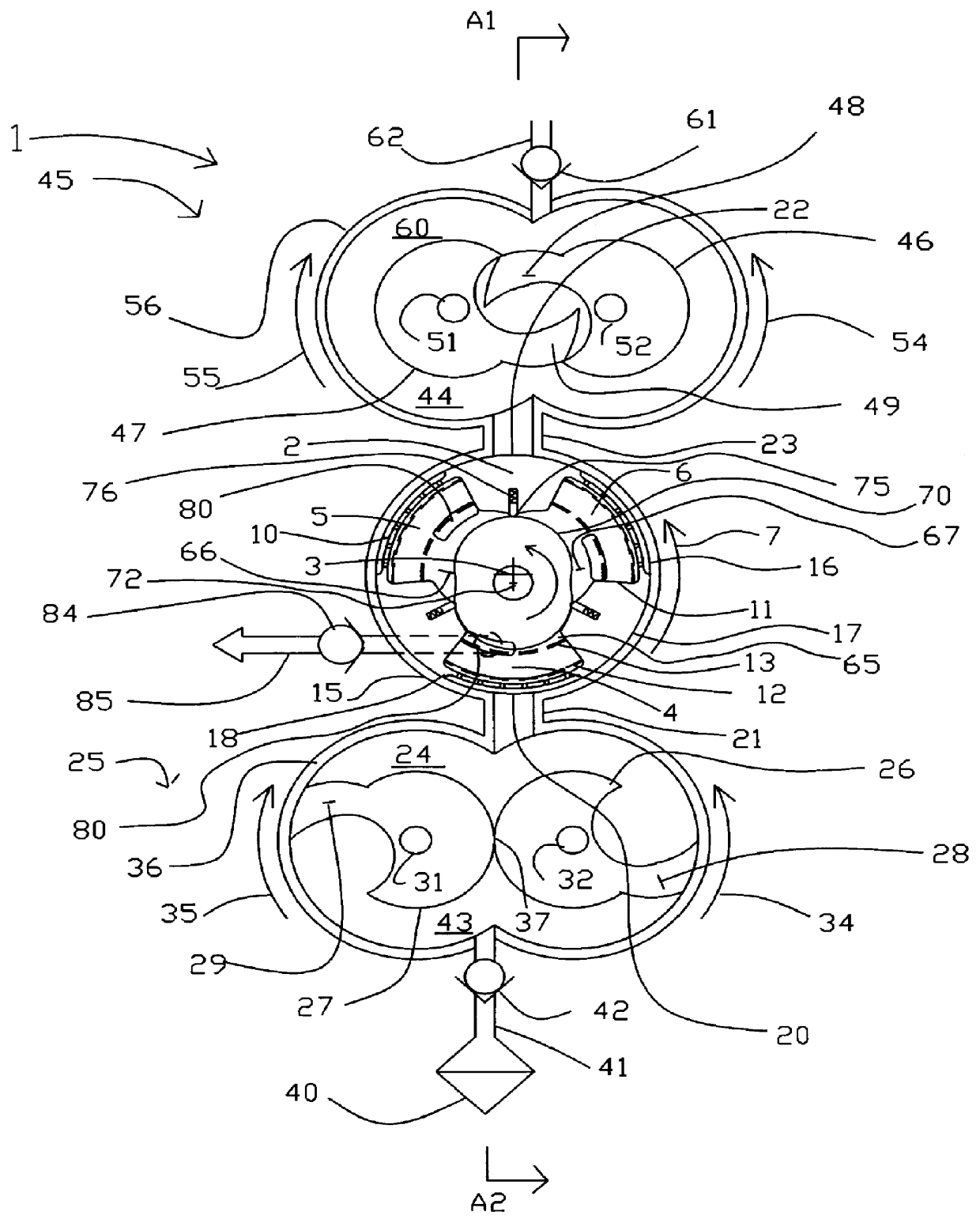
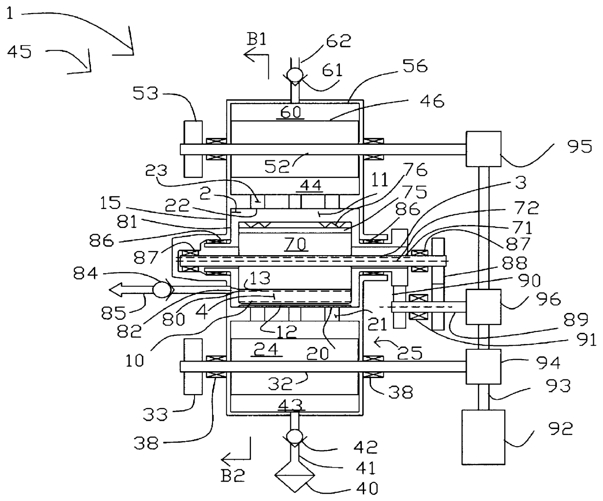
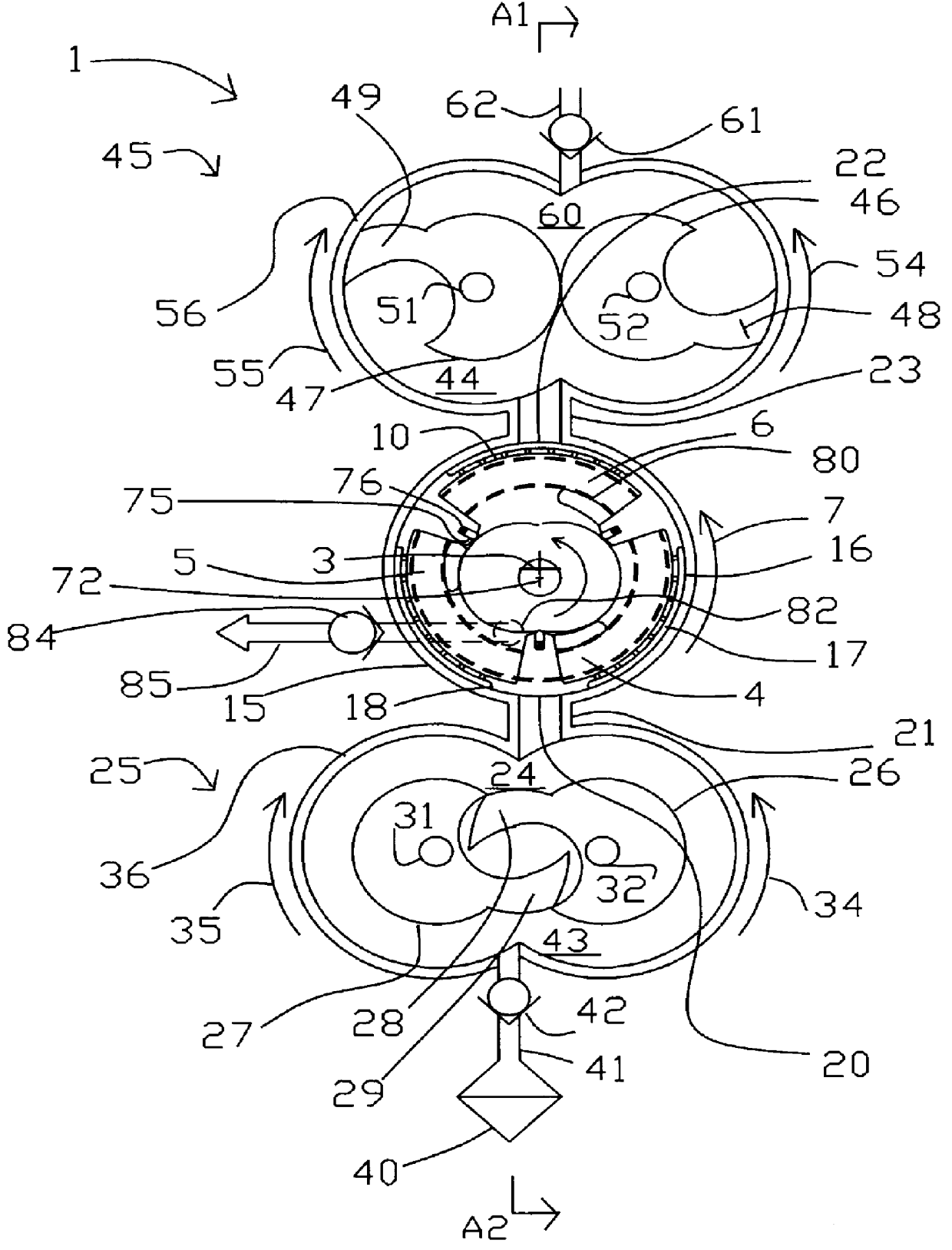
FIG. 5 shows an alternative six adsorber embodiment 200 for concentration of oxygen, based on a pressure waveform for each adsorber similar to that of FIG. 4. FIGS. 6 and 7 are respectively sections defined by arrows C1 and C2, and arrows D1 and D2, of FIG. 5, each with feed and exhaust claw pumps serving three of the six adsorbers.

Two sets of three adsorbers are operated with a claw feed pump and exhaust pump for each set of three adsorbers, with the pumps of the two sets of adsorbers being operated in staggered phase so that the total 6 adsorbers operate in the same PSA cycle but phased 60.degree. apart.

embodiment 1

Apparatus 200 is driven by motor 201, mechanically coupled by gearbox 202 and shaft 203 to adsorber rotor 204, by gearbox 206 and shaft 207 to feed pumps 208 and 209 in tandem, and by gearbox 216 and shaft 217 to exhaust feed pumps 218 and 219 in tandem. As with embodiment 1, gearbox ratios are selected so that the feed and exhaust pumps rotate at three times the rotational speed of the adsorber rotor.

Feed pumps 208 and 209 have rotors 222 and 223 defining intake chambers 224 and 225 and discharge chambers 226 and 227 respectively. Exhaust pumps 218 and 219 have rotors 232 and 233 defining intake chambers 234 and 235 and discharge chambers 236 and 237 respectively.

The unconventional claw pumps of embodiment 1 use external valves. However the claw pumps in embodiment 200 are more conventional in having inlet and outlet ports in their housing end plates, opened and closed by the rotor claws.

Feed air is introduced by intake filter 240 and infeed conduit 241 to feed pump intake ports 24...

embodiment 300

FIG. 9 shows the alternative use of a rotary multiport valve with throttle orifices for light reflux steps. In this embodiment 400 of rotor 204, the rotor is configured as an annulus containing six adsorbers 401, 402, 403, 404, 405 and 406. Reversing the arrangement of embodiment 300, the first ends of the adsorbers are radially outward and the second ends are radially inward. This embodiment has no light reflux (oxygen) expander, but instead uses a multiport valve to direct light reflux flow through orifices for equalization, cocurrent blowdown and purge steps.

Rotor 204 revolves within housing 320 with a narrow clearance 409 providing fluid sealing and valve porting for admission of feed and exhaust of second product (nitrogen waste), as set forth in discussion of FIGS. 5, 6 and 7. A stationary light reflux valve pintle 410, sealing to the inner wall of annular rotor 204 by a narrow clearance and sealing face 411. Sealing face 411 is depicted with a product delivery valve port 412,...


PUM


Abstract

Pressure swing adsorption separation of a feed gas mixture, to obtain a purified product gas of the less strongly adsorbed fraction of the feed gas mixture, is performed with a cooperating set of "N" adsorbers in a rotary assembly, with each adsorber communicating at its product end directly to a rotary cyclic displacement chamber, and at its feed end by rotary distributor valve ports to a rotary piston feed compressor and a rotary piston exhaust vacuum pump. The compressor and vacuum pump are integrated with the cycle, and rotate at "N" times the cycle frequency. Alternative adsorber configurations for high frequency operation are disclosed.

Description

The invention relates to gas separations conducted by pressure swing adsorption, and more particularly to oxygen separation from air and to hydrogen purification.Gas separation by pressure swing adsorption is achieved by coordinated pressure cycling and flow reversals over an adsorbent bed (or adsorber) which preferentially adsorbs a "heavy" or more readily adsorbed component relative to a "light" or less readily adsorbed component of the mixture. The total pressure is elevated during intervals of flow in a first direction through the adsorber from a first end to a second end of the adsorber, and is reduced during intervals of flow in the reverse direction. As the cycle is repeated, the less readily adsorbed component is concentrated in the first direction, while the more readily adsorbed component is concentrated in the reverse direction.A light product enriched in the light component is then delivered from the second end of the adsorber, while a heavy product enriched in the heavy...

Claims


Application Information

Patent Timeline
Patent Type & Authority Patents(United States)
IPC IPC(8): B01D53/04B01D53/047
CPCB01D53/06B01D53/0446B01D53/0462B01D53/047B01D2259/40007B01D2256/12B01D2256/16B01D2259/40005
Inventor KEEFER, BOWIE G.MCLEAN, CHRISTOPHER R.
Owner AIR PROD & CHEM INC
Why Eureka
Try Eureka