Optical fiber diffraction grating, a method of fabricating thereof and a laser light source

Inactive Publication Date: 2000-05-23
SUMITOMO ELECTRIC IND LTD
View PDF17 Cites 97 Cited by
  • Summary
  • Abstract
  • Description
  • Claims
  • Application Information

AI Technical Summary

Benefits of technology

In the laser source according to claim 7, the optical fiber diffraction grating defined by claim 1, i.e., the optical fiber diffraction grating which is formed by concentrically surrounding an optical fiber having a diffraction grating portion with a first coating portion consisting of a liquid crystal polymer having a thermal expansion coefficient with a sign opposite to that of the thermal expansion coefficient of the optical fiber so as to

Problems solved by technology

In an optical fiber diffraction grating laser using such a conventional optical fiber diffraction grating as an external resonance reflector for the laser, the oscillation wavelength of the laser varies with changes in ambient temperature, posing a problem in terms of stability.
However, in the method of prev

Method used


Image

  • Optical fiber diffraction grating, a method of fabricating thereof and a laser light source
  • Optical fiber diffraction grating, a method of fabricating thereof and a laser light source
  • Optical fiber diffraction grating, a method of fabricating thereof and a laser light source

Examples


first embodiment

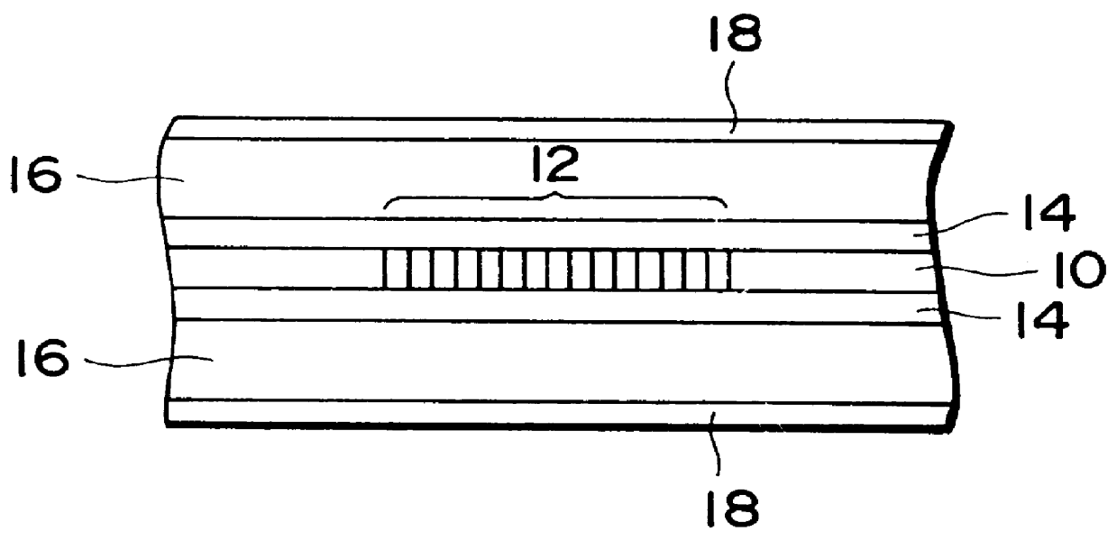
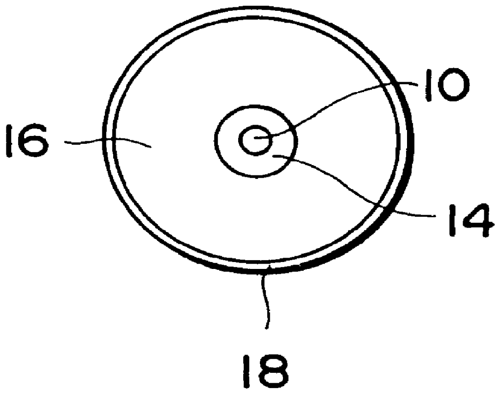
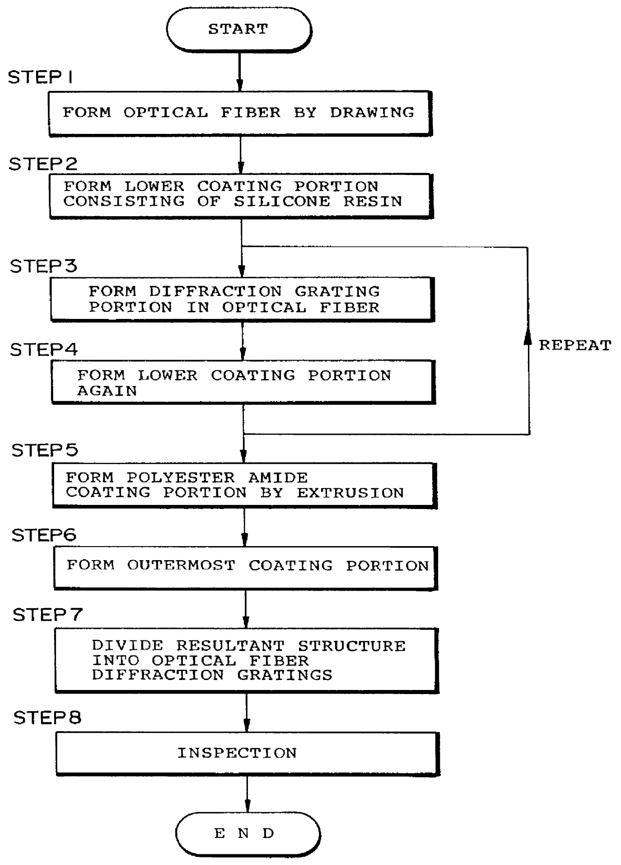
As described above, the optical fiber diffraction grating comprises the optical fiber 10 having the diffraction grating portion 12, the lower coating portion 14 consisting of the silicone resin and concentrically covering the optical fiber 10, the polyester amide coating portion 16, and the outermost coating portion 18 consisting of the colored UV curing resin. Both the optical fiber 10 and the lower coating portion 14 consisting of the silicone resin have positive thermal expansion coefficients. In contrast to this, the polyester amide coating portion 16 has a negative thermal expansion coefficient, e.g., a thermal expansion coefficient of -1.8.times.10.sup.-5 / .degree. C. to -7.2.times.10.sup.-6 / .degree. C. For this reason, the expansion / contraction of the optical fiber 10 and the lower coating portion 14 consisting of the silicone resin due to changes in temperature is canceled out by the expansion / contraction of the polyester amide coating portion 16 in the opposite direction,...

first application example

FIG. 3 shows the structure of a laser source according to the first application example. As shown in FIG. 3, in the laser source according to this application example, the exit end face of a laser diode 20 for emitting light is coated with an antireflection film 22 having a reflectance of about 5%. The exit end face of the laser diode 20 is optically coupled to one end portion of an optical fiber diffraction grating 26 according to the first application example through a coupling lens 24.

An optical connector 28 for connection to an optical fiber cable is attached to the other end portion of the optical fiber diffraction grating 26 for outputting a laser beam.

FIG. 4 is a graph showing the temperature dependence of the oscillation wavelength of the laser source in FIG. 3. The laser source according to this example uses the laser diode 20 as a laser medium, and the optical fiber diffraction grating 26 according to the above embodiment as an external resonance reflector. Variations in t...

second application example

FIG. 5 shows the structure of a laser source according to the second application example. As shown in FIG. 5, in the laser source according to this application example, one end of an optical fiber doped with a rare earth element, e.g., an EDF (Erbium Doped Fiber) 30 is coupled to an HR (Highly Reflective) mirror 32. This HR mirror 32 is optically coupled to a pumping light source 34 for emitting pumping light. The other end of the EDF 30 is optically coupled to the optical fiber diffraction grating 26 according to the above embodiment. This optical fiber diffraction grating 26 has a diffraction grating portion 28. An optical connector 40 for connection to the optical fiber cable is attached to the other end portion of the optical fiber diffraction grating 26 for outputting a laser beam.

As described above, according to the optical fiber diffraction grating laser of this application example, the optical fiber laser using the EDF 30 as a laser medium used the optical fiber diffraction ...


PUM


Abstract

PCT No. PCT/JP96/03000 Sec. 371 Date Jun. 16, 1997 Sec. 102(e) Date Jun. 16, 1997 PCT Filed Oct. 16, 1996 PCT Pub. No. WO97/14983 PCT Pub. Date Apr. 24, 1997A diffraction grating portion (12) is formed in an optical fiber (10), having a diameter of 125 mu m and serving to transmit light, along its optical axis. The optical fiber is concentrically surrounded by a lower coating portion (14) having an outer diameter of 300 mu m and consisting of a silicone resin. The lower coating portion is concentrically surrounded by a coating portion (16) having an outer diameter of 900 mu m and consisting of a liquid crystal polymer, e.g., polyester amide. The coating portion is further surrounded by an outermost coating portion (18) having an outer diameter of 1 mm and consisting of a UV curing resin colored for identification. Both the optical fiber (10) and the lower coating portion (14) have positive thermal expansion coefficients. In contrast to this, the coating portion (16) consisting of the liquid crystal polymer has a negative thermal expansion coefficient.

Description

The present invention relates to an optical fiber diffraction grating in which a diffraction grating portion for reflecting incident light having a specific wavelength is formed, a method of fabricating thereof, and an optical fiber diffraction grating laser using the optical fiber diffraction grating as an external resonance reflector.An optical fiber diffraction grating can output light having a specific reflection wavelength upon reception of incident light. Owing to this advantage, a great deal of attention has recently been paid to the optical fiber diffraction grating as an important optical part in a division multiplex transmission wavelength division multiplex optical transmission communication system which multiplexes and transmits optical signals having different wavelengths through one optical fiber.Such an optical fiber diffraction grating is generally constituted by a coating portion consisting of a plastic material and concentrically surrounding an optical fiber glass ...

Claims


Application Information

Patent Timeline
IPC IPC(8): H01S3/067H01S3/06G02B6/38
CPCG02B6/0218H01S3/0675G02B6/0219G02B6/3845
Inventor WAKAMI, TOSHINORISHIGEMATSU, MASAYUKITERASAWA, YOSHIAKIINOUE, AKIRASHIGEHARA, MASAKAZUIWASHIMA, TORU
Owner SUMITOMO ELECTRIC IND LTD
Why Eureka
Try Eureka