Mode field diameter conversion fiber, method for locally changing a refractive index of optical waveguides and method for fabricating optical waveguide preforms

a technology of optical waveguide and conversion fiber, which is applied in the field of fiber optics, can solve the problems of complicated fabrication of the mode field diameter conversion fiber and the narrow range of mode field diameter variation, and achieve the effect of avoiding deformation caused by mechanical stresses

Inactive Publication Date: 2000-09-26
VOLOKONNO OPTICHESKAYA TEKHNIKA KAPITAL +2
View PDF11 Cites 58 Cited by
  • Summary
  • Abstract
  • Description
  • Claims
  • Application Information

AI Technical Summary

Benefits of technology

In particular, to avoid deformations caused by mechanical stresses when an optical waveguide is fixed in two points, an auxiliary optical waveguide is spliced with the optical waveguide before the thermal diffusion.

Problems solved by technology

The problem with the mode field diameter conversion fiber is a complicated technology caused by a small coefficient of germanium diffusion to quartz glass, resulting in a prolonged heat treatment of the optical waveguide, required to produce a mode field diameter conversion fiber.
Apart from that, the diffusion occurs efficiently only at the temperature of 1600.degree. C. to 1800.degree. C. that is close to the melting point and, therefore, causes deformations in optical waveguides.
A disadvantage of the above prior art is a complicated fabrication of the mode field diameter conversion fiber and a narrow range of mode field diameter variation, which is caused by a limited concentration of fluorine that can be introduced into the core along with germanium.
Furthermore, the fluorine diffusion will unavoidably lead to the appearance, in such an optical waveguide, of regions with a decreased refractive index, which hampers coupling to conventional optical waveguides.
In the optical waveguide, an incoming beam and a beam reflected from the end face interfere, causing a periodic change in the refractive index.
Disadvantages of the above prior art method include a sophisticated process, a small change (.DELTA..about.10.sup.-6) in the refractive index, impossibility to vary a period of the grating produced, high cost and complexity of operating the apparatus implementing the method.
The above prior art method, however, suffers from an elaborated technology of locally changing the refractive index of an optical waveguide.
However, the process of locally changing the refractive index is rather complicated owing to use of the ultraviolet laser radiation and by virtue of the fact that a number of photosensitive types of optical waveguides is limited.
In addition, the employed ultraviolet lasers are relatively expensive, sophisticated in service, have insufficient reliability and their radiation is hazardous to human eye.
The double doping with germanium and fluorine significantly complicates the fabrication of optical waveguides for a mode field diameter conversion fiber.
A further disadvantage of this method is that it is impossible to control the law of changing the core refractive index along the optical fiber axis, which is defined by the temperature distribution within the heating apparatus and cannot be modified in the course of the process.
A further problem is that the optical waveguide undergoes deformation when heated, owing to relaxation of lateral stresses appearing when the optical waveguide is fixed.
However, fabrication of a preform from nitrogen-doped quartz glass is unfeasible under thermodynamic equilibrium conditions typical for this method.
The method, however, is technologically complicated since it does not employ process parameters in the preform synthesis, which would allow a reproducible control of the nitrogen concentration in the quartz glass, required to obtain a desired refractive index difference .DELTA.n between the optical waveguide core and cladding.

Method used


Image

  • Mode field diameter conversion fiber, method for locally changing a refractive index of optical waveguides and method for fabricating optical waveguide preforms
  • Mode field diameter conversion fiber, method for locally changing a refractive index of optical waveguides and method for fabricating optical waveguide preforms
  • Mode field diameter conversion fiber, method for locally changing a refractive index of optical waveguides and method for fabricating optical waveguide preforms

Examples


Embodiment Construction

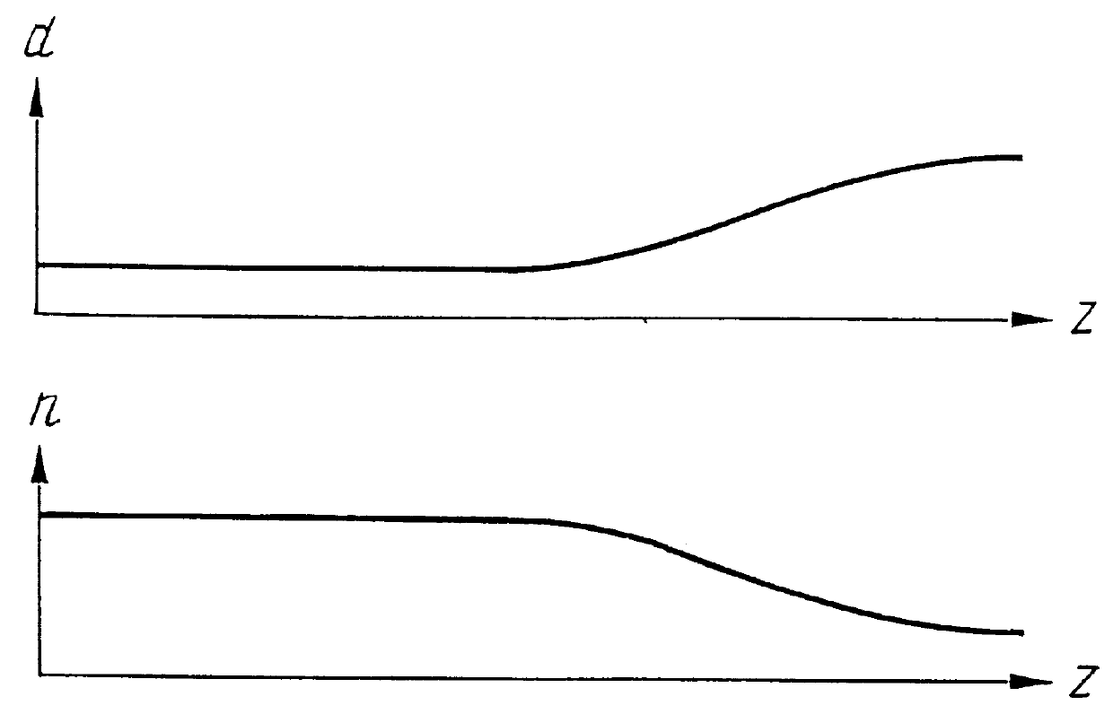
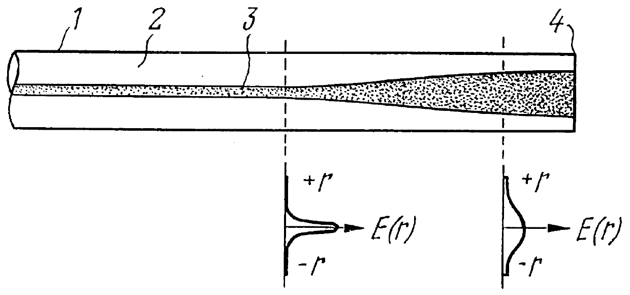
Referring to FIG. 1, a mode field diameter conversion fiber comprises a length of an optical waveguide 1 including a cladding 2 and a core 3, wherein a diameter d of the core 3 is increasing towards the end 4 of the length of the optical waveguide, while the effective refractive index n thereof is decreasing.

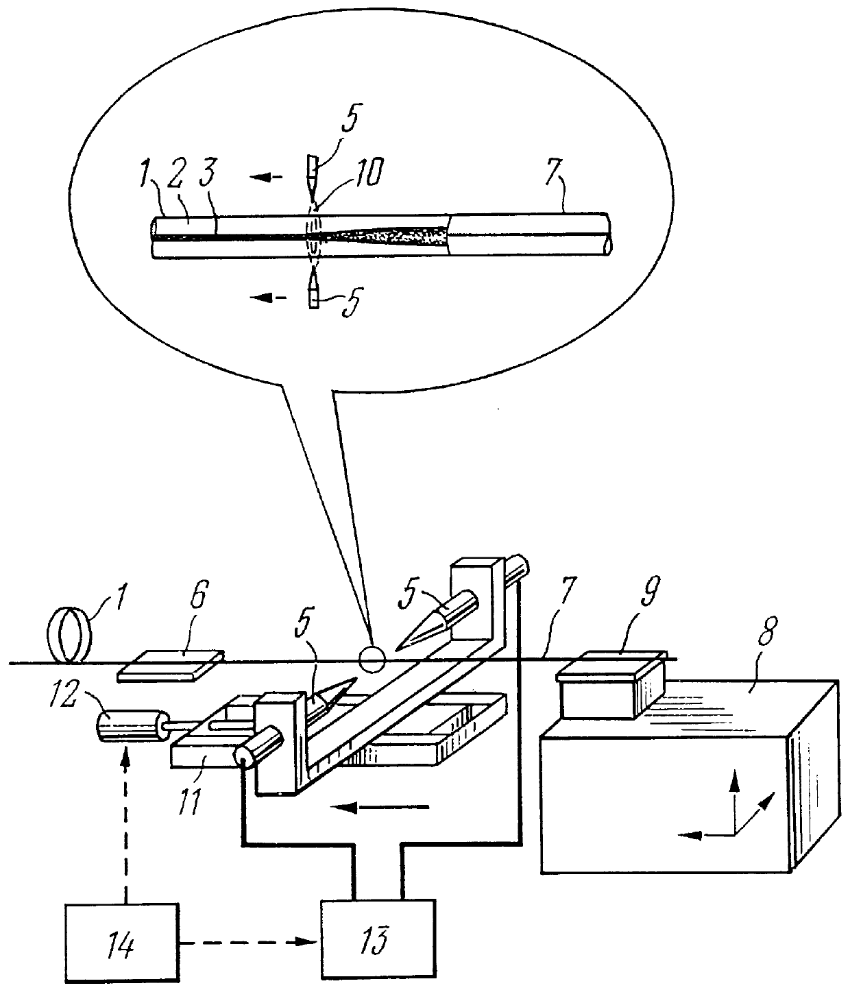
In an apparatus for fabricating a mode field diameter conversion fiber, using an electric arc (FIG. 2), electrodes 5 with sharpened ends are arranged at right angle to the axis of the length of the optical waveguide 1. The optical waveguide 1 is fixed by a clamp 6. An auxiliary optical waveguide 7 is secured in a three-coordinate micrometer positioner 8 with a clamp 9.

An electric arc 10 is displaced along the optical waveguide axis by a translator 11 with a step motor 12. The electrodes are connected to a power source 13 that sets the arc current. The electric arc displacement and current are controlled by a computer 14.

In an apparatus for fabricating a mode field diameter conve...


PUM


Abstract

PCT No. PCT / RU97 / 00278 Sec. 371 Date Jul. 9, 1998 Sec. 102(e) Date Jul. 9, 1998 PCT Filed Sep. 3, 1997 PCT Pub. No. WO98 / 28643 PCT Pub. Date Jul. 2, 1998The invention relates to fiber optics and can be employed in fiber radiation collimators, optical waveguide couplers, spectral filters, optical isolators, long-period gratings, dispersion compensators, cascade mode field diameter conversion fibers on simulated Raman effect, physical value sensors, radiation suppression units for predetermined wavelengths, and for smoothing the gain spectrum in erbium fiber amplifiers. The invention facilitates fabrication of optical waveguides and apparatuses based on them. To produce preforms for optical waveguides (1) by a plasma chemical vapor deposition method, molecular gaseous agents, fed to a substrate tube (24), are mixed so that less than five atoms of oxygen fall on every atom of silicon and more than one atom of nitrogen falls on every 1000 atoms of oxygen. The refractive index is locally changed by heating a length of an optical waveguide (1). This causes a local thermal diffusion of elements contained in a core (3) into a cladding (2), or vice versa. The length of the optical waveguide (1) is heated by current of an electric arc (10) or by radiation (16) of an infrared laser (15). The core (3) is doped with nitrogen at concentration from 0.01 at. % to 5 at. %. In the mode field diameter conversion fiber, a diameter of the core (3) changes along the length of the optical waveguide (1), increasing towards its end (4).

Description

1. FIELD OF THE INVENTIONThe present invention relates to fiber optics.2. BACKGROUND OF THE INVENTIONA conventional mode field diameter conversion fiber comprising a length of an optical waveguide including a quartz glass cladding and a germanium-doped quartz glass core, wherein the core diameter varies along the optical waveguide, increasing towards its end, is disclosed, e.g., by K. Shiraishi, Y. Aizava, S. Kawakami in the reference titled as "Beam Expanding Fiber Using Thermal Diffusion of Dopant" in IEEE Journal of Lightwave Technology, 1990, vol.8, No.8, p.1151-1161. In the mode field diameter conversion fiber of the above reference, the longitudinal variation in a core diameter is provided owing to redistribution of the radial doping profile, which forms the refractive index structure of the optical waveguide, in the process of thermal diffusion of germanium.The problem with the mode field diameter conversion fiber is a complicated technology caused by a small coefficient of g...

Claims


Application Information

Patent Timeline
Patent Type & Authority Patents(United States)
IPC IPC(8): G02B6/255G02B6/26C03B37/018C03B37/10G02B6/00G02B6/02G02B6/14
CPCG02B6/02147G02B6/2552G02B6/02095G02B6/14
Inventor DIANOV, EVGENY MIKHAILOVICHGOLANT, KONSTANTIN MIKHAILOVICHKARPOV, VLADIMIR IVANOVICHPROTOPOPOV, VLADIMIR NIKOLAEVICHGREKOV, MIKHAIL VLADIMIROVICHKHRAPKO, ROSTISLAV RADIEVICH
Owner VOLOKONNO OPTICHESKAYA TEKHNIKA KAPITAL
Why Eureka
Try Eureka