Differential wideband vibration sensor

a wideband vibration sensor and wideband technology, applied in the field of accelerometers, can solve the problems of high bandwidth devices, difficult process of calibrating any given accelerometer to detect vibration as differentiated against a "zero" vibration level, and limited sensitivity, so as to achieve cost-effective, automatic self-calibration during operation, and eliminate the effect of costly precision tuning of individual units

Inactive Publication Date: 2001-04-24
INTERSCI
View PDF15 Cites 26 Cited by
  • Summary
  • Abstract
  • Description
  • Claims
  • Application Information

AI Technical Summary

Benefits of technology

An important embodiment of the invention includes an associated mechanical and electrical reference structure to allow for differential measurements with the accelerometer. The use of a reference allows calibration of the sensor to an electronic and mechanical "zero" of vibration. This simplified measurement approach eliminates costly precision tuning of individual units and allows for cost effective, automated self-calibration during operation.

Problems solved by technology

The type of accelerometers mentioned above have good sensitivity at low frequencies but limited sensitivity at high frequencies, although they result in higher bandwidth devices than open loop devices.
In addition, due to mechanical and electronic manufacturing variations from one accelerometer to the next, the process of calibrating any given accelerometer to detect vibration as differentiated against a "zero" vibration level is difficult without means to establish such a differential reading.
One fundamental problem of implementing a vibration sensor is that most of the time the fabrication process used to implement the sensor is incompatible with the most common processes used to implement the standard electronics associated with the sensor.
This type of multi-die implementation, however, results in higher costs and lower yield since a more complex multi-die packaging is needed.

Method used


Image

  • Differential wideband vibration sensor
  • Differential wideband vibration sensor
  • Differential wideband vibration sensor

Examples


Embodiment Construction

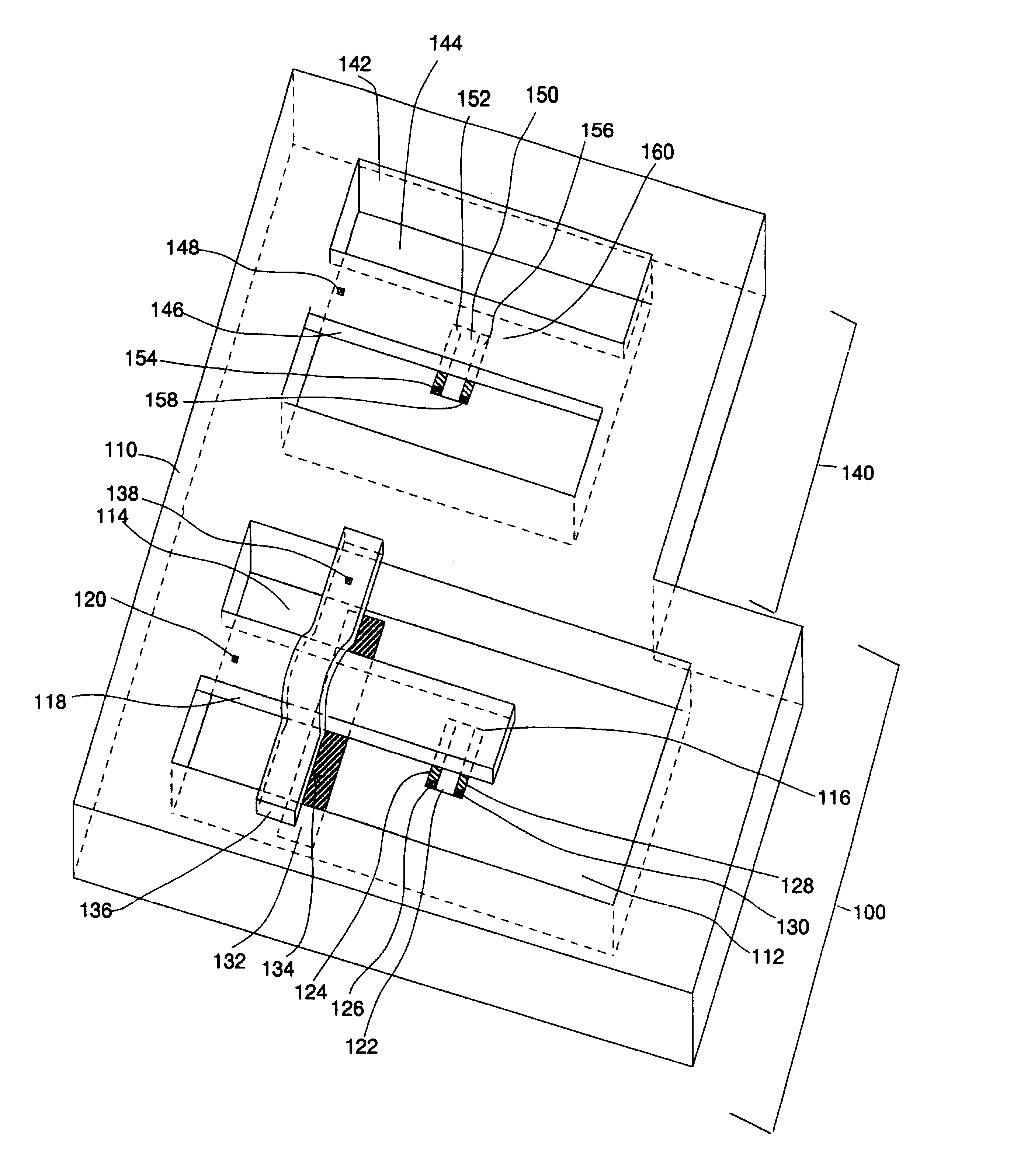
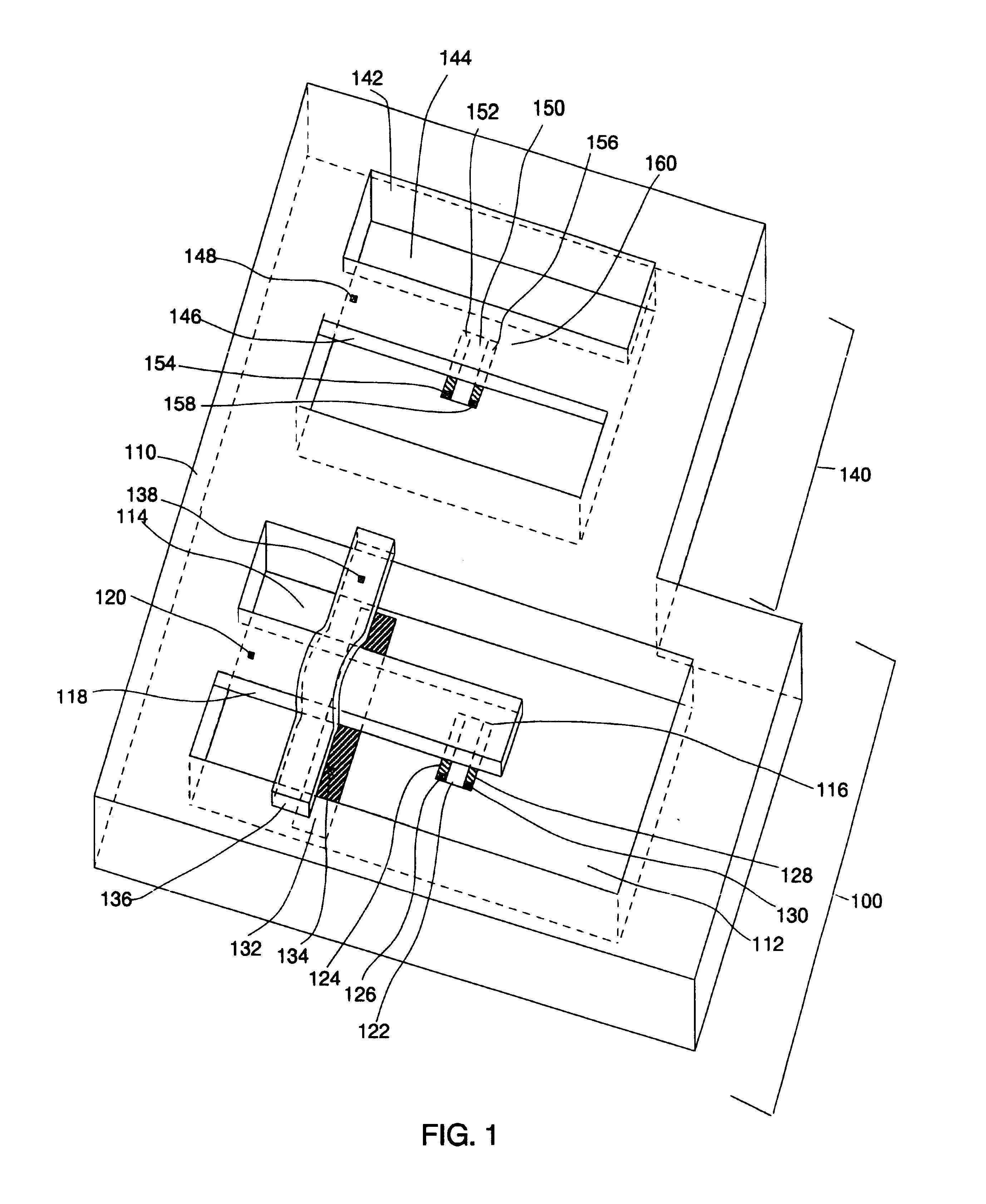
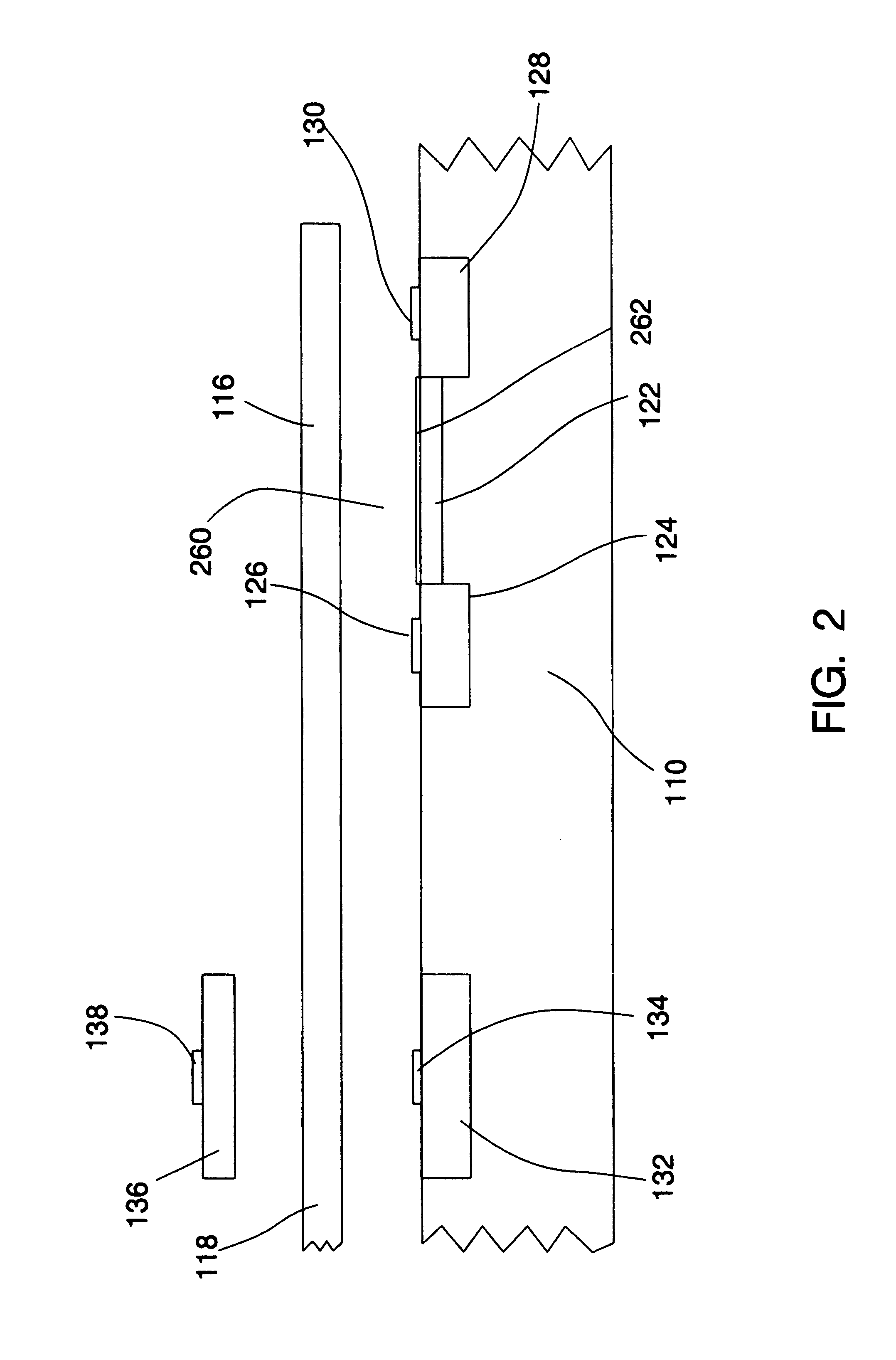
A preferred embodiment of the present invention is depicted in FIG. 1. Referring to FIG. 1, vibration sensor 100 comprises a base 110 with a cavity 112 and a cavity floor 114 in a central region of base 110. A moveable suspended mass 118 such as the illustrated cantilever beam, thinner than the depth of the cavity, projects horizontally from a top surface of one end of base 110, partially extending over central cavity 112. An electrically-conductive suspended mass (cantilever beam) contact pad 120 is positioned on the top surface of moveable suspended mass 118. A gate region 116, is defined as the free end of moveable suspended mass 118 immediately above a channel 122, i.e., as that region of moveable suspended mass 118 that is sufficiently proximate to said channel 122 so as to electromagnetically interact with said channel 122 in a substantial manner. An external power means is connected to cantilever beam contact pad 120 in order to deliver specified voltages to gate region 116 o...


PUM


Abstract

This invention relates to an apparatus for making highly sensitive differential measurements of acceleration. The vibration sensor includes the use of moveable gate field effect transistors to sense the motion of a cantilever beam relative to the motion sensed by a reference structure, it also includes an actuator element formed by a pair of electrodes actuating electrostatically on the beam. A feedback control loop is also included for force balance operation resulting in a very wide dynamic range for the sensor.

Description

This invention relates to the field of accelerometers, and particularly to enhancing the high frequency capabilities of accelerometers, and to differential measurement capabilities of accelerometers.The concept of a moveable gate Field Effect Transistor (FET) has been extensively studied and reported in literature. A number of devices have been disclosed that make use of a moveable gate FET for building accelerometers.Force balance feedback control of vibration sensors has been used in seismometers and in accelerometers for attaining increased bandwidth and dynamic range. A number of devices using this approach have been routinely demonstrated and its theory of operation is well understood. Several seismometer and accelerometer manufacturers base their designs on this principle.The fabrication of a silicon accelerometer using wafer bonding techniques is disclosed in great detail in U.S. Pat. No. 5,095,752 and No. 5,417,312. In these invention disclosures a relatively large mass made...

Claims


Application Information

Patent Timeline
Patent Type & Authority Patents(United States)
IPC IPC(8): G01P15/13G01P15/12
CPCG01P15/124G01P15/131
Inventor GUTIERREZ, ADOLFO O.EDMANS, DANIEL M.CORMEAU, CHRISTOPHER
Owner INTERSCI
Why Eureka
Try Eureka