Thermal enhancement approach using solder compositions in the liquid state

a technology of liquid state and composition, applied in the direction of printed electric component incorporation, electrical apparatus construction details, lighting and heating apparatus, etc., can solve the problems of insufficient power dissipation, inability to efficiently dissipate heat energy, and inability to meet the much higher power allotment being contemplated for future designs, and achieve low thermal resistance

Inactive Publication Date: 2001-08-28
IBM CORP
View PDF28 Cites 154 Cited by
  • Summary
  • Abstract
  • Description
  • Claims
  • Application Information

AI Technical Summary

Benefits of technology

is to provide a low thermal resistance path between the IC chip and its associated heat exchanger.
It is yet another object of the present invention to provide an IC chip package in which thermal mismatches between the chip, its associated heat exchanger, and an interfacing thermal conducting material are minimized.
Yet another object of the present invention is to provide a more efficient way to dissipate heat from an integrated circuit chip through its associated heat exchanger and the joint bond there between.
This method further comprises providing an elastomeric ring between the cover and the substrate top surface to non-hermetically sealed and semi-hermetically sealed electronic modules, such that the ring eliminates solder outflow and prohibits environmental degradation to soldered surfaces.

Problems solved by technology

Current electronic module designs do not efficiently dissipate heat energy at rates beyond power levels of 25 to 50 Watts.
Beyond these levels expensive methods of water cooling are necessary to minimize the external thermal resistance and maximize the thermal gradient, thus enhancing heat flow.
The power dissipation is inherently limited by both internal and external thermal resistance to heat flow.
Thermal pastes currently in use as low thermal resistant conductors between an IC chip and its heat exchanger are adequate to satisfy the thermal dissipation requirements at the present state of the art, however, they are inadequate for the much higher power allotments being contemplated for future designs.
Although there are many materials, especially metals, that have excellent thermal conductivity satisfying the thermal dissipation requirements, most of the metals in the solid state induce intolerable stresses in the multi-chip modules during thermal cycling.
The result is IC chip cracking, unacceptable C-4 solder deformation, and excessive fatigue damage leading to early failure.
There is also the associated problem of operational thermal cycling or mini-cycles that are common among devices employing power saving schemes, such as CMOS technology parts.
The alternating power demands by the IC chip exacerbate the power dissipation requirements and enhance device fatigue.
The mixture does not provide the melting and solidifying properties in the IC chip operational temperature range for which the material must have the properties of releasing or absorbing sufficient heat to counteract the effects of mini-cycles.
The solder is not designed to melt and re-solidify under the IC chip operational temperature range which would absorb and reject heat.
Thus, this art does not have the capacity for heat generation and subtraction during the rise and fall of temperature due to mini-cycles.
The solder, however, remains a distance away from the chip and would not be able to significantly attenuate the temperature cycling due to mini-cycles even if the solder were suitable and had the requisite thermodynamic properties to meet the requirements of power dissipation in the proper temperature range.

Method used


Image

  • Thermal enhancement approach using solder compositions in the liquid state
  • Thermal enhancement approach using solder compositions in the liquid state
  • Thermal enhancement approach using solder compositions in the liquid state

Examples


embodiment

Preferred Embodiment

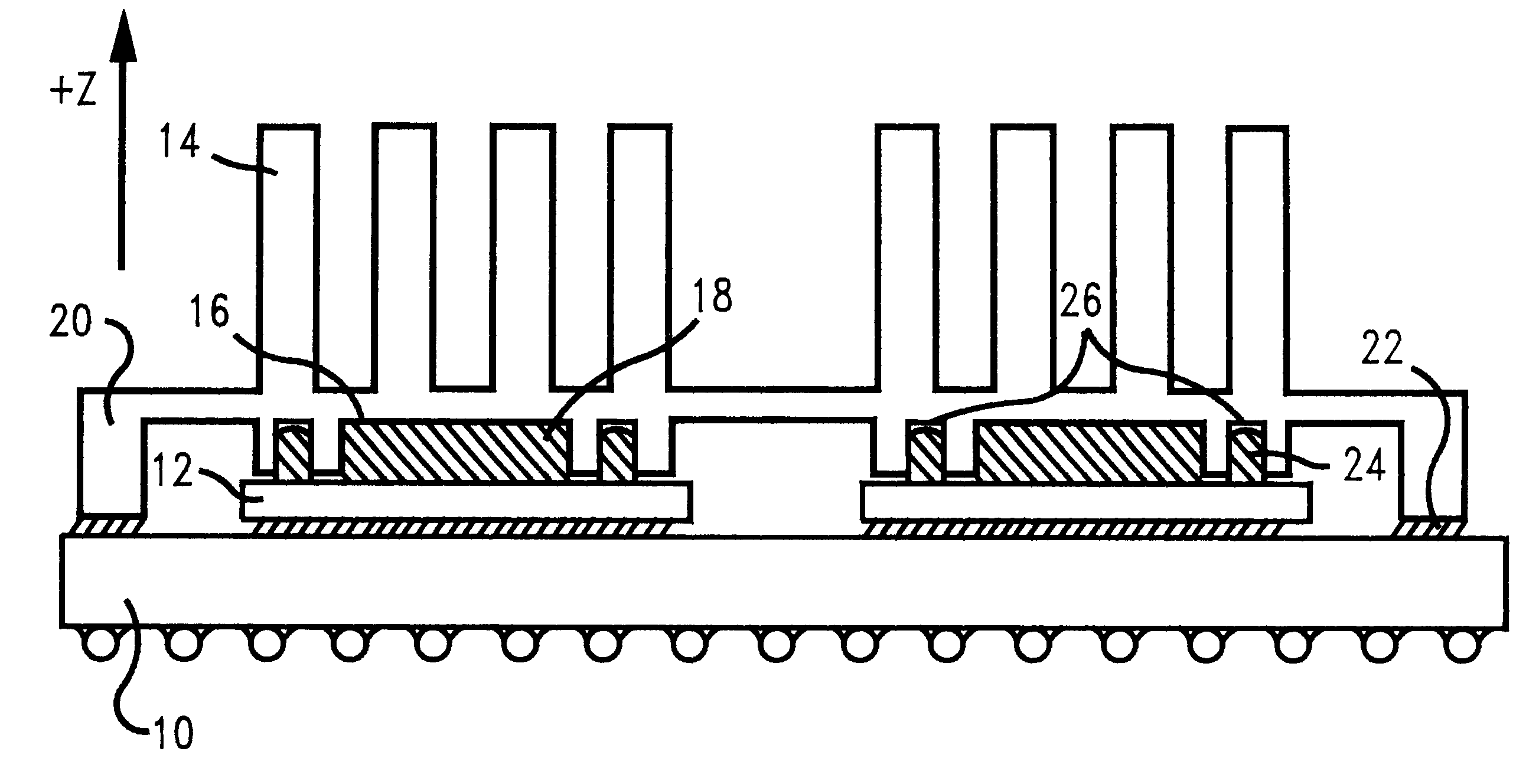
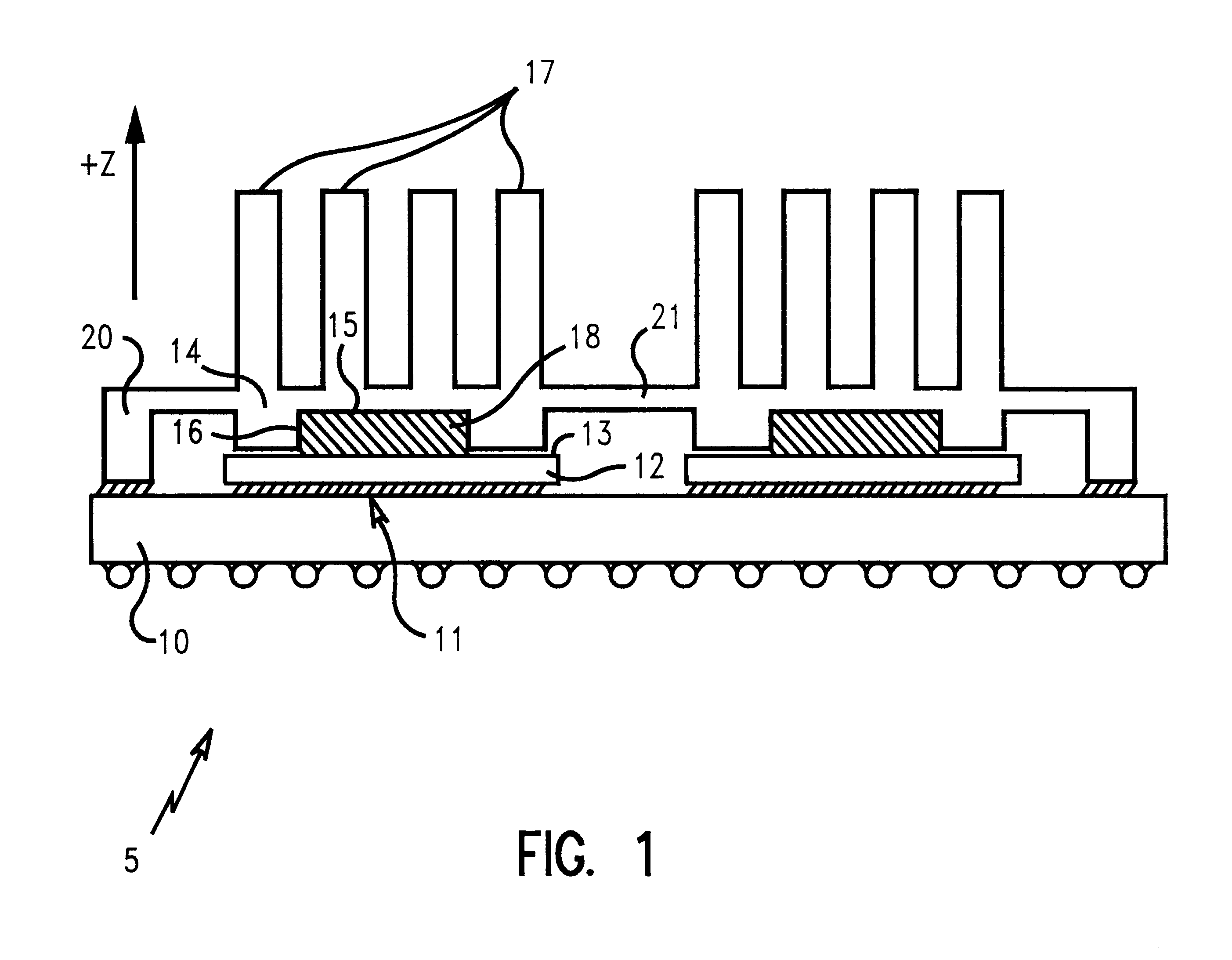
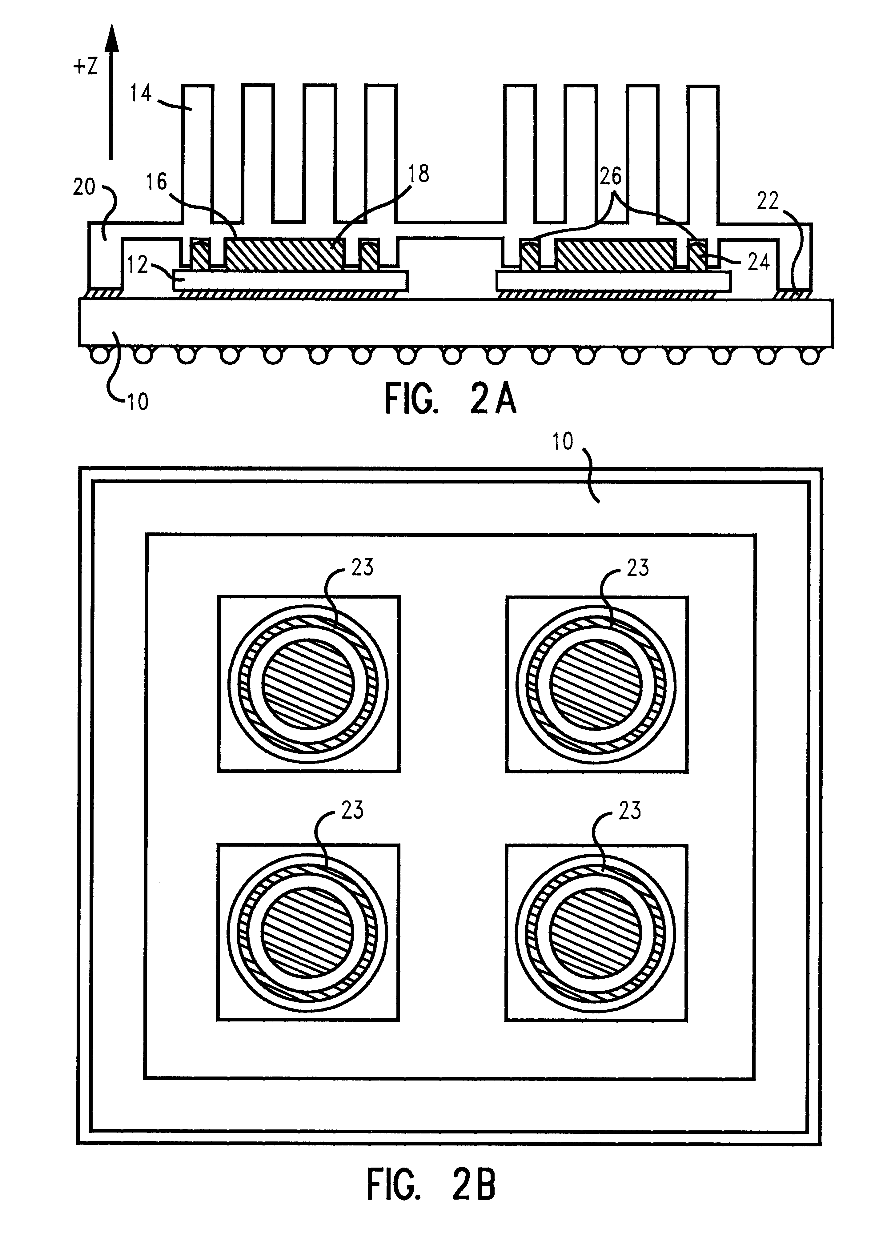
FIG. 1 depicts a multi-chip electronic module package 5. Integrated circuit chip 12 with top surface 13 is shown connected to substrate 10 through C-4 attachments 11. Heat exchanger 14 is located above the IC chip and has a cavity 16 with bottom surface 15 for placement of the thermal conducting material. The heat exchanger 14 is structured to have considerable mass and surface area in order to efficiently transfer the heat energy from the IC chip to the air. Depicted in FIG. 1 is heat exchanger 14 with solid fingers 17 arranged for optimum heat dissipation to the ambient air. Ceramic cap 20 and heat exchanger 14 are either attached such that they form a single cover over the electronic module's IC chip and substrate, or initially formed as a single structure. Cap 20 is bonded to the top surface of substrate 10. A bonding or solder composition 18 is affixed within cavity 16 of heat exchanger 14. The heat exchanger element over each individual IC chip is connected...


PUM

PropertyMeasurementUnit
liquidus temperatureaaaaaaaaaa
eutectic temperatureaaaaaaaaaa

Abstract

Solder compositions are introduced to interface between an IC chip and its associated heat exchanger cover. The solder compositions have a solidus-liquidus temperature range that encompasses the IC chip operational temperature range. The solder composition has the desired property of absorbing and rejecting heat energy by changing state or phase with each temperature rise and decline that result from temperature fluctuations associated with the thermal cycles of the integrated circuit chips. A path for high thermal conduction (low thermal resistance) from the IC chip to the heat exchanger to the ambient air is provided by an electronic module cover, configured as a cap with a heat exchanger formed or attached as a single construction, and made of the same material as the substrate, or made with materials of compatible thermal coefficients of expansion to mitigate the effects of vertical displacement during thermal cycling. The cap-heat exchanger cover is constructed to be compliant, and to contact both the IC chip and substrate.

Description

1. Field of the InventionThis invention relates to heat dissipation of a semiconductor device or electronic module, and in particular to a method and means for accomplishing such dissipation and reducing stresses caused by thermal gradients by employing an electronic module cap and heat exchanger as a single structure, and a semi-molten material between the IC chip and its associated heat exchanger to melt and solidify in the IC chip operational temperature range in order to release and absorb heat energy and create a low thermal resistance path to the heat exchanger.2. Description of Related ArtTechnological advancements in semiconductor device design and fabrication have significantly increased integrated circuit chip power requirements, and these requirements continue to climb. In order to accommodate these enhanced power requirements, it has become necessary to find more efficient ways to dissipate heat through the electronic packages and their associated heat exchangers.Current...

Claims


Application Information

Patent Timeline
Patent Type & Authority Patents(United States)
IPC IPC(8): H01L23/367H01L23/34H01L23/427H01L23/373
CPCH01L23/3675H01L23/3736H01L23/4275H01L2924/01327H01L2924/01322H01L2924/16251H01L2924/15311H01L2224/73253H01L2224/73204H01L2224/32245H01L2224/32225H01L2224/16225H01L2924/00013H01L2924/09701H01L2924/00H01L2224/29099
Inventor ATWOOD, EUGENE R.BENENATI, JOSEPH A.DIGIACOMO, GIULIOQUINONES, HORATIO
Owner IBM CORP
Why Eureka
Try Eureka