
Cone beam volume CT angiography imaging system and method

a ct angiography and volume technology, applied in tomography, instruments, applications, etc., can solve the problems of inability to provide a complete set of data to precisely reconstruct the object, unavoidable distortion in the non-central transverse plane, and trade-off between high longitudinal resolution and fast volume scanning

Inactive Publication Date: 2001-10-02
UNIVERSITY OF ROCHESTER
View PDF10 Cites 102 Cited by
  • Summary
  • Abstract
  • Description
  • Claims
  • Application Information

AI Technical Summary

Benefits of technology

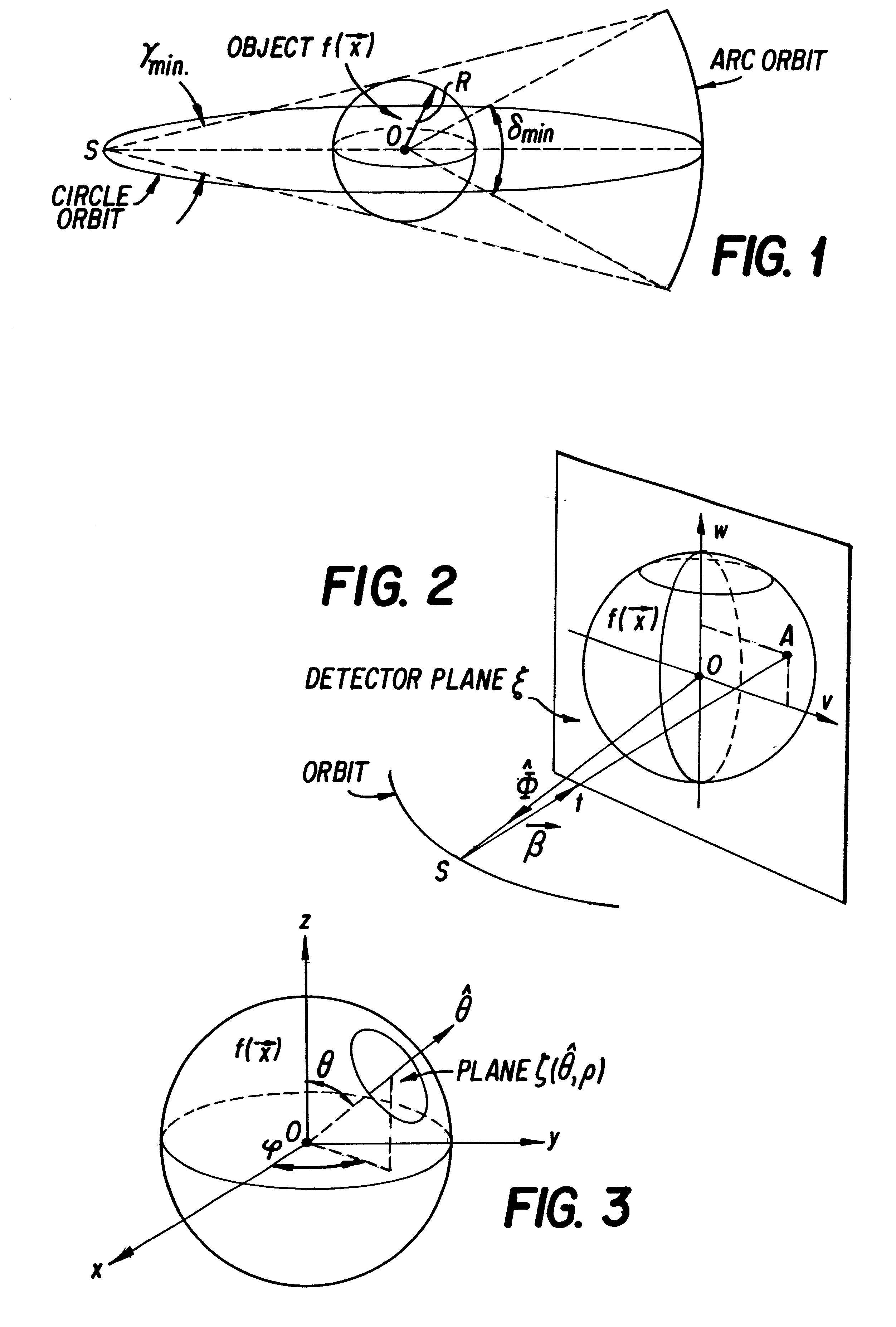
Still more particularly, it is an object of this invention to provide for a circle-plus-arc data acquisition geometry for use with volume CT scanner using a cone-beam x-ray source and a 2-D detector in which a standard CT gantry is utilized without introducing mechanical complexity to achieve exact 3-D reconstructions of an object.
Using the IV-VTDA system of the present invention, efficient contrast and spatial resolution is provided in order to visualize all vascular vessels presently amenable to interventional techniques. In addition, the IV-VTDA system of the present invention covers a much larger segment of the human body in the direction orthogonal to the slices within a single scan (approximately 3-4 times larger) than a spiral CT can cover, and without sacrificing image quality.

Problems solved by technology

Conventional CT scanners use a fan-shaped x-ray beam and one-dimensional detector in order to reconstruct a single slice with a single scan of an object However, current CT technology is limited by a trade-off between high longitudinal resolution and fast volume scanning.
Single circle cone-beam geometry, in which the source always lies on a circle, cannot provide a complete set of data to exactly reconstruct the object.
's algorithm causes some unavoidable distortion in the non-central transverse planes, as well as resolution degradation in the longitudinal direction.
Thus, errors can be introduced by the implementation of the Gangreat method that can be greater than those produced using the Feldkamp, et al. method and such errors are not correlated with the cone-beam angle.
However, such an integer requirement condition is too restrictive for practical application since the only known source point geometry which meets that condition is a straight line.
It cannot result in exact reconstruction and it is not acceptable in many clinical applications when the cone angle is large.
The incompleteness of the projection data results in some unavoidable blurring in the planes away from the central z plane and a resolution loss in the z direction (i.e., Feldkamp, et al.
The reconstruction error due to the incompleteness of the projection data could be up to 50% of the signal when using Feldkamp, et al.
Projection images using such standard projectional techniques do not provide sufficient information with which to detect and completely characterize all vascular lesions.
That lack of complete data impairs the ability of the physician to determine the optimal therapeutic procedure.
Obviously, an inappropriate choice of intervention based on improper knowledge of the patient's anatomy can lead to unnecessary interventions, a sub-optimal outcome, injury or death.
Second, IA-DSA images are of reduced usefulness due to vessel overlap, particularly when non-selective injections are used.
However, even with multiple views, the number of views is limited, which often results in non-detected lesions because of the failure to achieve orthogonal projection and overlap.
Consequently, the angiographic procedure can become prolonged, increasing patient morbidity from lengthened catherterization time, increasing contrast as well as the radiation dose, while also increasing procedure costs.
There is also an added risk of complications related to percutaneous cannulation of an artery and the manipulation of the IA catheters and wires in critical vessels which are often affected by vascular disease.
The risk of procedure related vascular injury and stroke is also present, with major morbidity.
Moreover, such angiography technique is frequently repeated as the vascular disease progresses, thus multiplying costs and risks.
However, in addition to the shortcomings inherent with all types of DSA, there are two additional important technical deficiencies which are specific to IV-DSA.
First, image misregistration often occurs due to patient motion.
Such misregistration too often masks the vascular anatomy to be imaged.
Second, there is an inability to attain a sufficiently high concentration of contrast media through intravenous injection to overcome the quantum noise inherent in the DSA technique.
Due to those deficiencies, the resulting image is generally of poor quality and, thus, IV-DSA has become an infrequently used clinical technique.
Such techniques have been only partially successful in reducing the severity of motion artifacts and in improving problems with vessel overlaps.
One of the drawbacks of IA-VTDA is that it is based upon IA injections, which are generally much more invasive than IV injections.
One of the difficulties of using IV-VTDA in place of IA-VTDA is that IV injections result in a much lower signal compared to IA injections.
First, the long volume scan time of CTA limits the rate of contrast injection and at least a 30 second breathhold is required by the patient Therefore, CTA is more sensitive to patient motion than IV-VTDA techniques.
Also, due to tube loading limitations, the resolution in the section direction of CTA is practically limited, and small-vessel resolution may be limited by partial volume effects.
Furthermore, IV-VTDA can also be used for lower extremity angiography where spiral CTA cannot be used because of the limited tube capacity and total amount of contrast media which can be safely administered to a patient.
However, current MRA procedures have some deficiencies, including limited spatial resolution, overestimation of stenosis and other artifacts, particularly at regions of flow disturbances, tradeoffs between making the field of view (FOV), signal to noise ratio and spatial resolution and relatively long scanning times, which make it sensitive to patient motion.
However, compared to IV-VTDA, a principle limitation of ultrasound is the need for an appropriate acoustic window.
Intervening air or bone prevent the acquisition of diagnostic information at a substantial number of potential vascular sites.
For that reason, ultrasound has a primary diagnostic role in the carotid and lower extremity arteries, but is not useful in adult (closed fontanelle) skull and central chest areas and is limited in use in the deep abdomen.
Other disadvantages of ultrasound include a limited FOV, dependence on Doppler angle, dependence on operator skill, and the inability to distinguish total occlusion from severe stenosis as well as a poor 3-D depiction of the anatomy for surgical planning.

Method used


Image

  • Cone beam volume CT angiography imaging system and method
  • Cone beam volume CT angiography imaging system and method
  • Cone beam volume CT angiography imaging system and method

Examples


Embodiment Construction

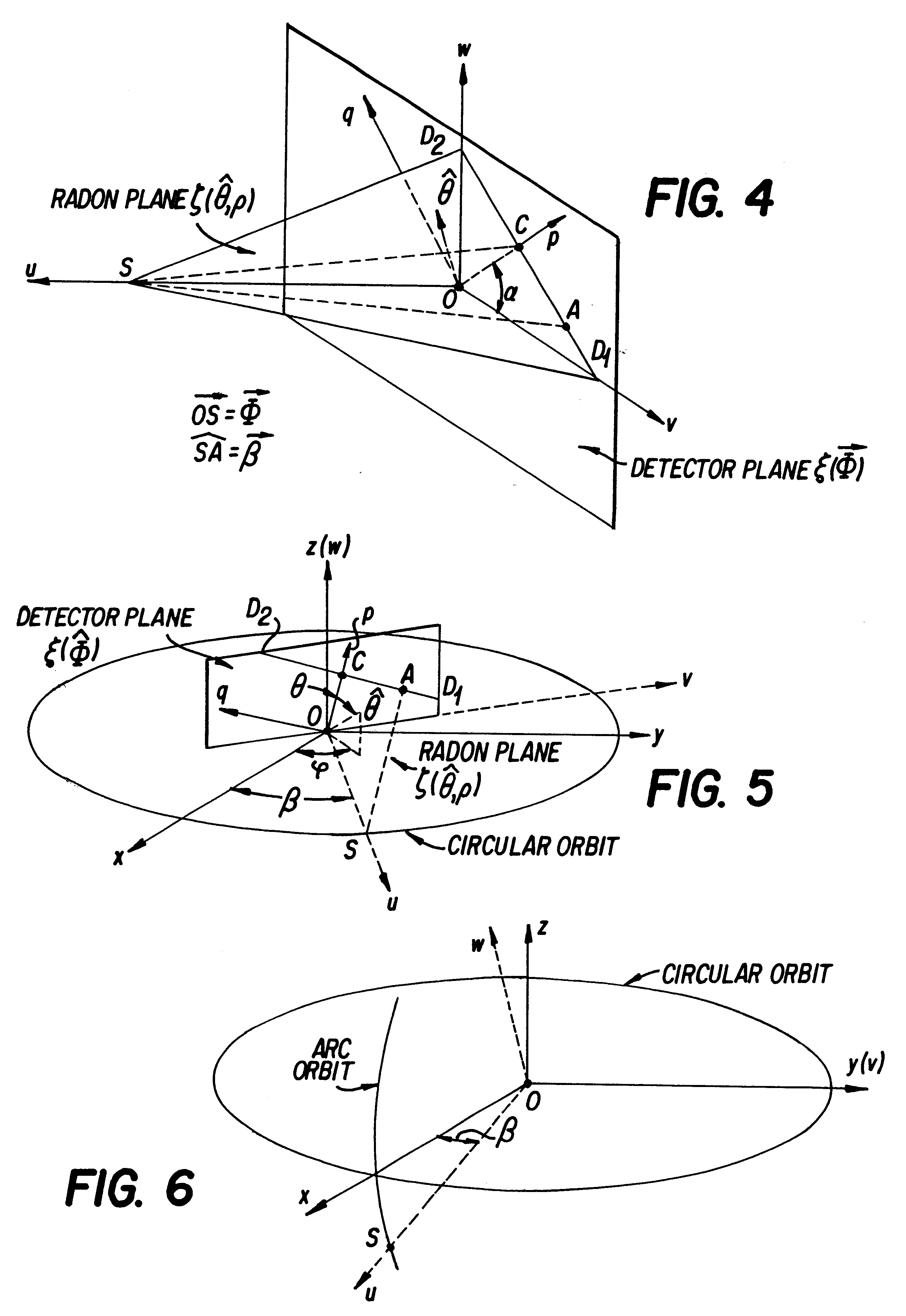
With the relationship between the upq--0 and the uvw--0 coordinate systems (See FIG. 4), ##EQU21##

and variable substituting, ##EQU22##

As is known in the prior art, great computational efficiency and accuracy can be obtained by swapping the integral with the derivative in Equation 9. With Equation 10 in mind, by putting Equation 17 into Equation 9 and swapping the integral with the derivative, ##EQU23##

Since the partial derivatives ##EQU24##

on the right-hand side of Equation 18 need to be calculated only once, the computational complexity is significantly reduced.

APPENDIX B

To fill the Radon cube (.theta.,.phi.,.rho.) with the projection data from the circular orbit, the transformation function should be found between the local uvw--O coordinates and the absolute xyz--O coordinates (see FIG. 5). The circular orbit lies in the xy plane and the focal point S will be restrained on this orbit The angle between the x-axis and the vector OS is defined as .beta. and the angle between the p-a...


PUM


Abstract

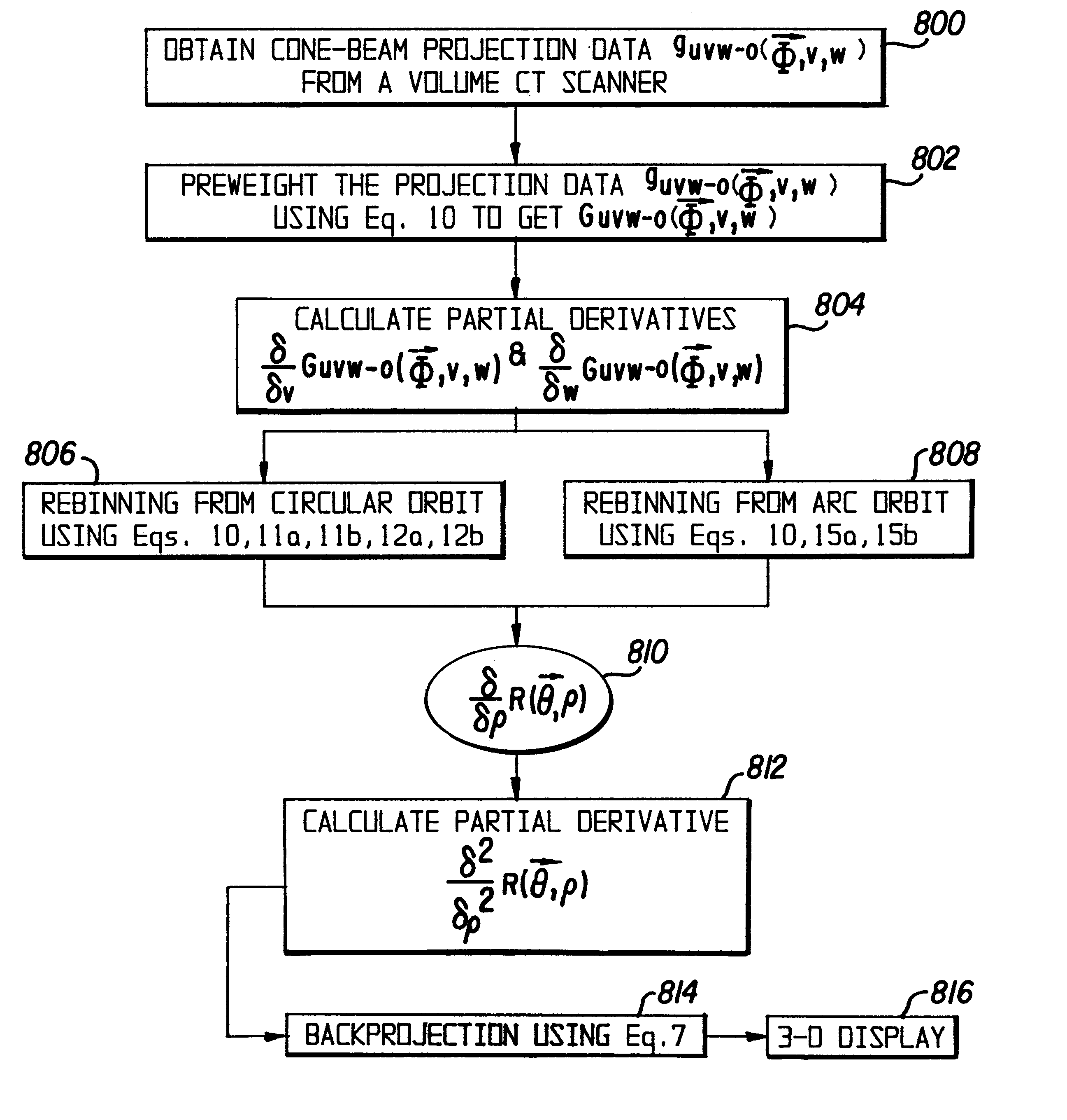
Only a single IV contrast injection with a short breathhold by the patient is needed for use with a volume CT scanner which uses a cone-beam x-ray source and a 2-D detector for fast volume scanning in order to provide true 3-D descriptions of vascular anatomy with more than 0.5 lp / mm isotropic resolution in the x, y and z directions is utilized in which one set of cone-beam projections is acquired while rotating the x-ray tube and detector on the CT gantry and then another set of projections is acquired while tilting the gantry by a small angle. The projection data is preweighted, partial derivatives are calculated and rebinned for both the circular orbit and arc orbit data The second partial derivative is then calculated and then the reconstructed 3-D images are obtained by backprojecting using the inverse Radon transform.

Description

The present invention is directed to a method of and system for computed tomography (CT) density image reconstruction. More particularly, the present invention is directed to the three-dimensional reconstruction from two-dimensional projections acquired with x-ray cone-beam CT and single photon emission computed tomography (SPECT) scanners. Even more particularly, the present invention is directed to a method of and system for intravenous volume tomographic digital angiography imaging.For about the past twenty years, computerized tomography has revolutionized diagnostic imaging systems as well as non-destructive test imaging techniques. Conventional CT scanners use a fan-shaped x-ray beam and one-dimensional detector in order to reconstruct a single slice with a single scan of an object However, current CT technology is limited by a trade-off between high longitudinal resolution and fast volume scanning. One method which has been utilized to address the shortcomings of CT scanner te...

Claims


Application Information

Patent Timeline
Patent Type & Authority Patents(United States)
IPC IPC(8): A61B6/03
CPCA61B6/4447A61B6/027Y10S378/901
Inventor NING, RUOLA
Owner UNIVERSITY OF ROCHESTER
Learn More