Method for forming reflowed solder ball with low melting point metal cap

a technology of reflowed solder ball and metal cap, which is applied in the direction of resistive material coating, printed circuit assembling, final product manufacturing, etc., can solve the problems of limiting the yield of cards, insufficient process improvements alone, and high cost of products

Inactive Publication Date: 2002-02-05
ULTRATECH INT INC
View PDF13 Cites 57 Cited by
  • Summary
  • Abstract
  • Description
  • Claims
  • Application Information

AI Technical Summary

Benefits of technology

Conventional methods of making masks, such as, molybdenum masks, holes or openings are formed by photomasking and etching both sides of the mask. This electrochemical etch biases gives rise to a structure of the etched hole where the hole diameter decreases, from either surfaces and reaches a minimum within the hole, giving an appearance of a knife edge. Because the thickness of the metal mask is approximately same as

Problems solved by technology

However, increases in circuit density produce a corresponding challenge to improve chip and chip connections in order to remain competitive.
Process improvements alone are not sufficient to increase both yield and reliability of these products.
Another limiting factor for use of these methods is difficulty in testing and/or burning-in of these mounted chips; this limits the card yield thus making the product expensive.
Yet another shortcoming is that rework is economically unfeasible.
These limitations necessitates use of a C4 like technology for joining chips directly on card.
Presently, there are two problems that limit the use of current C4 technology for 2nd or higher level assembly, i.e., for Direct Chip Attach (DCA) on card.
First, it limits the 2nd level interconnection to Pin-Through-Hole (PTH) technology and precludes the use of cost effective, space saving Surface Mount technology (SMT), because a joining temperature higher than melting point of the SMT solder is required.
Second, the relatively high joining temperature (340.degree. C.-380.degree. C. ) will char the card organics.
This structure does show a hierarchy of solder material, however, in this structure

Method used


Image

  • Method for forming reflowed solder ball with low melting point metal cap
  • Method for forming reflowed solder ball with low melting point metal cap
  • Method for forming reflowed solder ball with low melting point metal cap

Examples


example 1

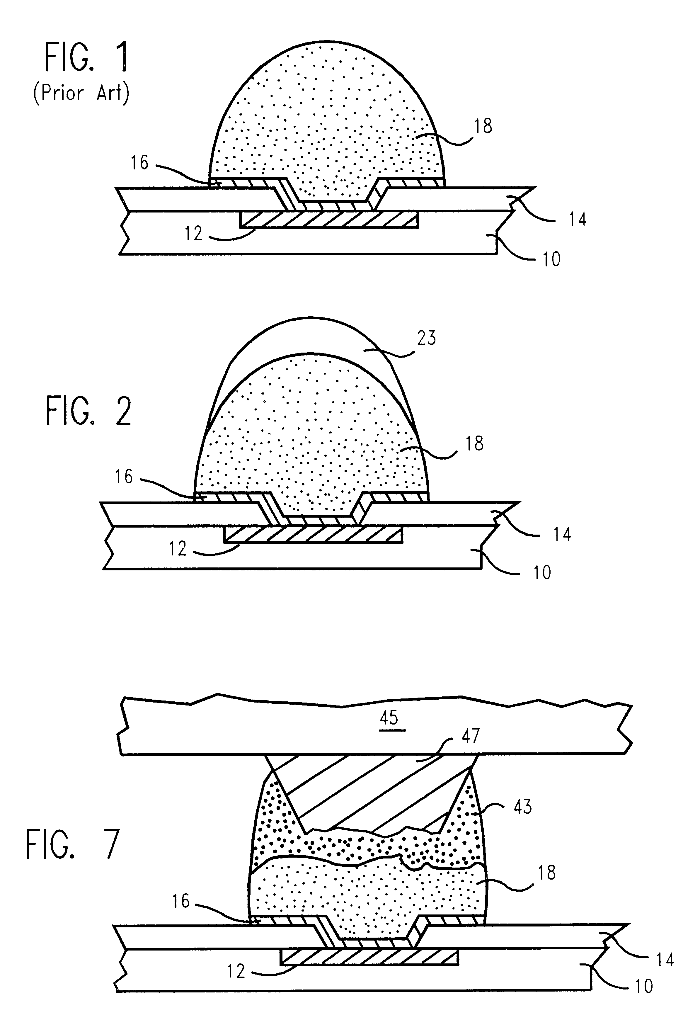
Semiconductor modules were made using the structure and process of this invention. On a convention solder ball 18, a capping layer of tin 23, was formed. The deposited capping layer of pure tin was between about 0.5 to about 2.0 mil thick, and it was deposited by evaporation. The amount of tin to be deposited on the solder ball 18, was determined by the volume of eutectic solder that is required to completely cover the exposed copper conductors 47, in card or substrate 45. The width and thickness of the copper conductor and the solder mask opening determines the surface area and hence the required eutectic volume. A 20 to 35 cubic mil of eutectic solder 43, volume is preferred for an original 40 to 100 cubic mil of high melt solder ball 18, volume.


PUM

PropertyMeasurementUnit
Fractionaaaaaaaaaa
Fractionaaaaaaaaaa
Fractionaaaaaaaaaa

Abstract

A method and structure for a solder interconnection, using solder balls for making a low temperature chip attachment directly to any of the higher levels of packaging substrate is disclosed. After a solder ball has been formed using standard methods it is reflowed to give the solder ball a smooth surface. A layer of low melting point metal, such as, bismuth, indium or tin, preferably, pure tin, is deposited on the top of the solder balls. This structure results in localizing of the eutectic alloy, formed upon subsequent low temperature joining cycle, to the top of the high melting solder ball even after multiple low temperature reflow cycles. This method does not need tinning of the substrate to which the chip is to be joined, which makes this method economical. It has also been noticed that whenever temperature is raised slightly above the eutectic temperature, the structure always forms a liquid fillet around the joint with copper wires. This liquid fillet formation results in substantial thermal fatigue life improvement for reduced stress at interface; and secondly, provides an easy means to remove chip for the purpose of chip burn-in, replacement or field repairs.

Description

The present invention relates generally to a new structure and method for capping of solder balls with a cap of at least one low melting point metal. More particularly, the invention encompasses a structure where the already reflowed solder balls are capped with at least one layer of tin. A method for such tin capping is also disclosed.Semiconductor devices are becoming smaller and more dense with the evolution of new technology. However, increases in circuit density produce a corresponding challenge to improve chip and chip connections in order to remain competitive. Chip manufacturers are therefore constantly challenged to improve the quality of their products by identifying and improving their products. Whereas significant process improvements are being made by reducing process variability. Process improvements alone are not sufficient to increase both yield and reliability of these products.Electronic products typically comprise of plurality of components. The packaging of these...

Claims


Application Information

Patent Timeline
IPC IPC(8): H01L21/60H01L21/02H01L23/498H01L21/48H01L23/48H05K3/34
CPCH01L21/4853H01L23/49816H01L24/11H01L24/12H05K3/3436H01L2224/0401H01L2224/05171H01L2224/05184H01L2224/05644H01L2224/05647H01L2224/05666H01L2224/11472H01L2224/1308H01L2224/13082H01L2224/131H01L2224/13109H01L2224/13111H01L2224/13113H01L2224/13609H01L2924/01006H01L2924/01013H01L2924/01022H01L2924/01027H01L2924/01028H01L2924/01029H01L2924/01042H01L2924/01047H01L2924/01049H01L2924/0105H01L2924/01051H01L2924/01073H01L2924/01074H01L2924/01075H01L2924/01078H01L2924/01079H01L2924/01082H01L2924/01083H01L2924/01322H01L2924/01327H01L2924/14H01L2924/19041H01L2924/19043H05K3/3463H05K2201/10992H05K2203/0435H01L2924/00013H01L2924/01005H01L2924/01024H01L2924/01033H01L2924/014H01L2224/136Y10T29/49144H01L2924/00014H01L2224/13099H01L2224/05671H01L2924/15787Y02P70/50H01L2924/00H01L2924/013
Inventor DALAL, HORMAZDYAR MINOCHERBITAILLOU, ALEXISFALLON, KENNETH MICHAELGAUDENZI, GENE JOSEPHHERMAN, KENNETH ROBERTPIERRE, FREDERICROBERT, GEORGES
Owner ULTRATECH INT INC
Why Eureka
Try Eureka