High temperature vacuum furnace

a vacuum furnace and high temperature technology, applied in the direction of muffle furnaces, furnace heating elements, furnaces, etc., can solve the problems of insufficient uniform distribution of radiant energy from all surfaces for achieving the precision required, prone to sag under high temperatures between spaced apart supports, and inability to meet the needs of precision, etc., to achieve the effect of better uniformity

Inactive Publication Date: 2002-02-19
PVT
View PDF29 Cites 17 Cited by
  • Summary
  • Abstract
  • Description
  • Claims
  • Application Information

AI Technical Summary

Benefits of technology

Accordingly, it is a general object of the present invention to provide an electric resistance vacuum furnace suitable for heating a workload to high temperatures with better uniformity and for cooling the workload and furnace without damage to component parts of a recirculating cooling system.

Problems solved by technology

While prior art electric vacuum furnaces as above-described are satisfactory for many heat treating processes, they are lacking in certain design features which significantly improve efficiency in the process.
Heating elements of thin rectangular or elliptical cross sections are prone to sag under high temperatures between spaced apart supports because of low section modulus.
The rectangular and elliptical elements also inherently lack even distribution of emitted radiant energy from all surfaces for achieving the precision demanded.
The above-described heating element designs choke a significant percentage of the emitted radiant energy which reduces the effective surface area and results in higher element temperatures causing creep, sagging and non-uniform heating.
Hence, the temperature of the workload will not be of optimal uniformity and a relatively long heat treating cycle time is required.
When quenching fluid is recirculated in the furnace through a heat exchanger at completion of the heat treating phase, the extremely hot fluid returning to the heat exchanger may heat seals and other components therein beyond their design limits causing permanent damage and leakage.

Method used


Image

  • High temperature vacuum furnace
  • High temperature vacuum furnace
  • High temperature vacuum furnace

Examples


Embodiment Construction

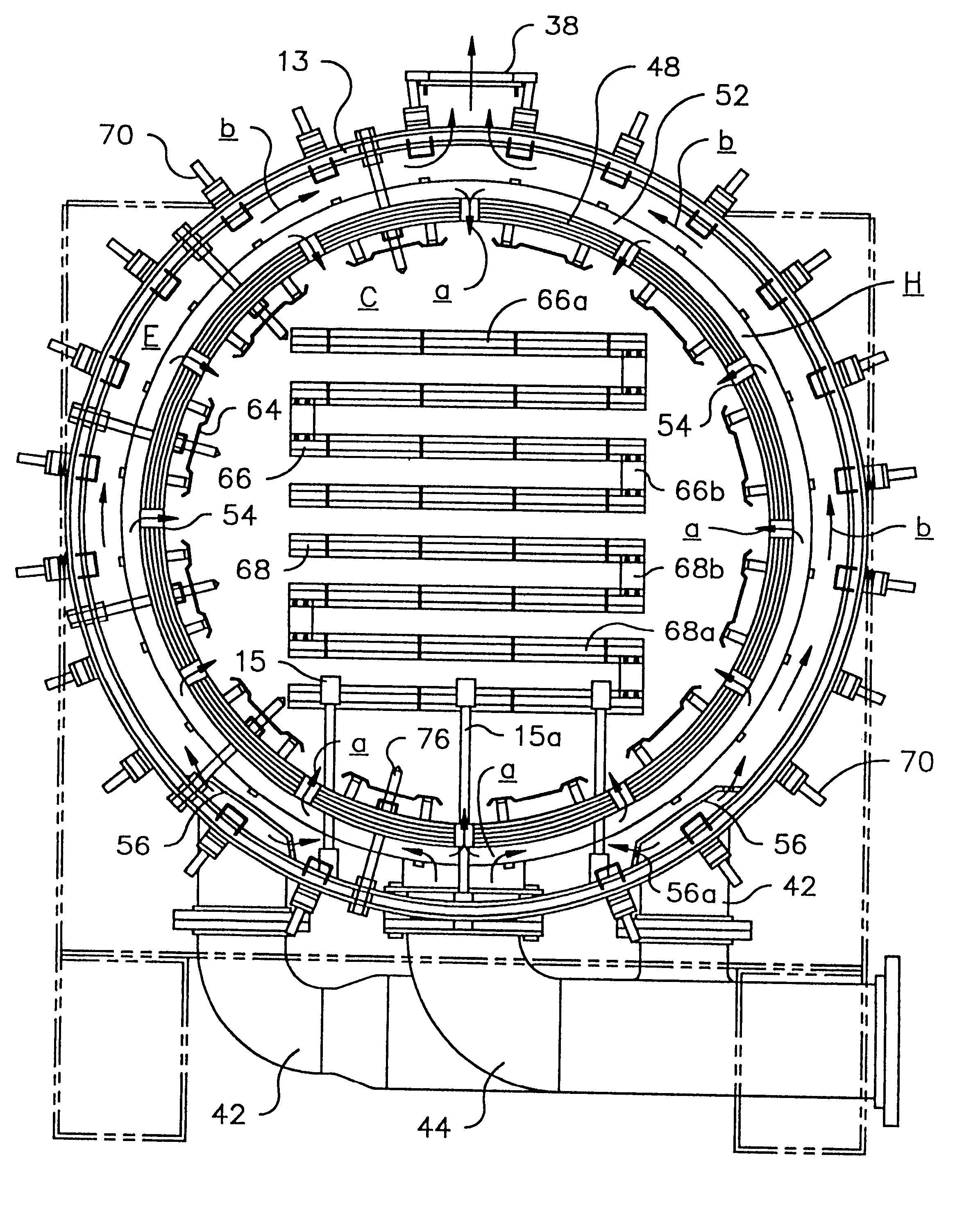
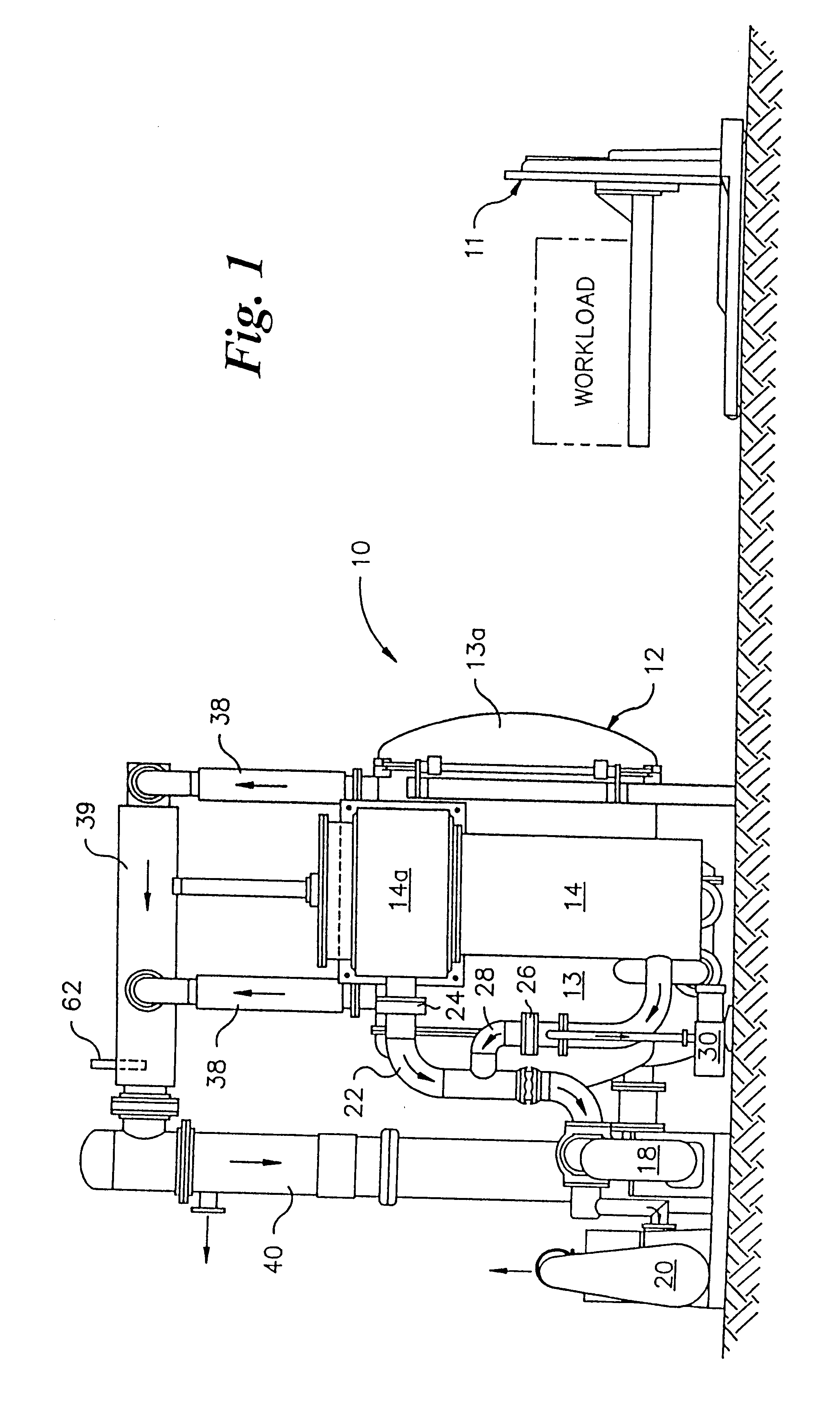
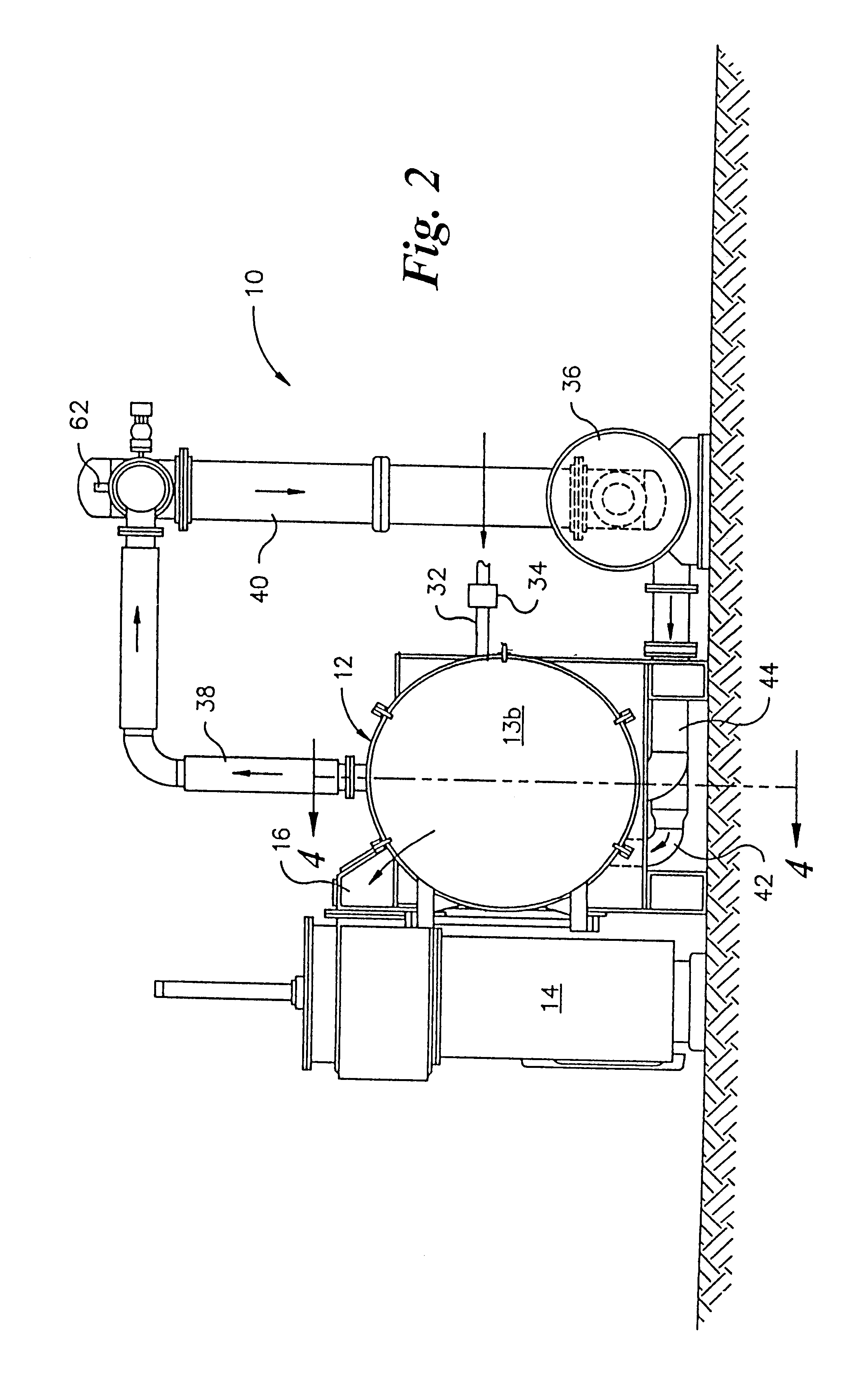
Referring now to the drawings wherein like reference numbers or characters denote like or corresponding parts throughout the several views, FIGS. 1-3 show a high temperature vacuum heat treating system according to the invention indicated generally be the numeral 10 comprising a water-cooled electric vacuum furnace 12 for receiving a workload and a loader truck 11 on tracks 11 a for positioning the workload therein. Furnace 12 includes a double-walled cylindrical vessel 13 closed at both ends by hinged double-walled front and rear loading doors 13a and 13b forming a vacuum-tight chamber. Cooling water is circulated between the double walls of vessel 13 and doors 13a, 13b by an exterior pump and heat exchanger not shown. A workload support is provided within the work space having three horizontal parallel rails 15 extending lengthwise and supported by axially spaced vertical rods 15a fixed to the bottom of vessel 13.

Vessel 13 is evacuated by a water-cooled oil diffusion pump 14, such...


PUM


Abstract

An electric resistance high temperature vacuum furnace having radiant heating units evenly spaced around the sides and ends of the furnace hot zone. Pairs of units are automatically regulated both radially and longitudinally according to the temperature required by the workload in the hot zone. The units each comprise parallel aligned elements electrically connected in series at their one ends. Each element has lengthwise surfaces angularly disposed from each other to form a beam structure of high section modulus for stiffness and resistance to sagging. Also, the angles of the element surfaces facing a heat-reflective assembly substantially enable all of the energy radiated toward the assembly to be reflected into the hot zone in addition to the direct radiation from the surfaces facing the hot zone. The furnace includes a re-circulating cooling system for rapid cooling of the furnace and workload. An inert cooling fluid bypasses the hot zone, passing instead around the outside of the heat assembly and through a heat exchanger until the circulated fluid temperature drops below the maximum tolerated by all component parts in the cooling system, after which the fluid passes directly through the hot zone.

Description

BACKGROUND OF THE INVENTION1. Field of the InventionThe present invention relates generally to electric resistance vacuum heat treating furnaces; and more particularly to improvements in a high temperature electric resistance vacuum furnace suitable for heat treating processes, such as brazing, tempering, degassing, sintering and hardening, in which the hot zone is heated by radiant energy and cooled by recirculated fluid.2. Description of the Prior ArtElectric vacuum heat treating furnaces typically consist of a cylindrical water-cooled vessel containing heating elements forming a hot zone for receiving a workload to be heat treated. An example of such a furnace is disclosed in U.S. Pat. No. 3,438,618 to Seelandt in which a cylindrical vessel contains a retort of separate upper and lower water-cooled, U-shaped shells with end walls movable into side-by-side relationship to form a box-like chamber. Radiant heating elements line each shell in transverse planes axially spaced along th...

Claims


Application Information

Patent Timeline
Patent Type & Authority Patents(United States)
IPC IPC(8): H05B3/62F27B21/00F27D15/00F27D3/00F27B5/05
CPCH05B3/62F27B21/00F27D2003/004F27D15/00
Inventor ASHBURN, LENNIE L.
Owner PVT
Why Eureka
Try Eureka