
Enhancing filtration yields in tangential flow filtration

Inactive Publication Date: 2002-02-26
PARKER INTANGIBLES LLC
View PDF15 Cites 103 Cited by
  • Summary
  • Abstract
  • Description
  • Claims
  • Application Information

AI Technical Summary

Benefits of technology

The invention generally relates to the filtration of liquids, more particularly to high precision separation suitable for use in the pharmaceutical and biotechnology industries. The invention is especially applicable to filtration through a porous membrane sheet or a porous hollow fiber column. With the invention, a variety of separation techniques are handled in a yield-enhancing manner and can be automated, including having the separation proceed until a desired level of concentration or other characteristic or parameter is attained. The invention enhances separation processes such as microfiltration, microparticle coating and washing, ultrafiltration, diafiltration and certain preparative chromatography applications. It also improves yield in automated viral infection of mammalian cells such as in gene therapy research and development, as well as rapid cell separation, protein clarification and protein concentration.
Another object of the present invention is to provide an improved concentration system or method for adjusting filter retentate output flow in order to maintain optimal product flow in response to changing product characteristics, e.g. increase in fluid viscosity due to removal of solvent.

Problems solved by technology

However, filtration devices tend to clog when used over an extended period of time and must be timely replaced.
Clogging of a filtration device occurs when the membrane pores become obstructed, typically with trapped cells, particulate matter, cell debris or the like.
This clogging of the pores results in a decreased liquid flow across the porous membrane sheet or hollow fiber column wall.
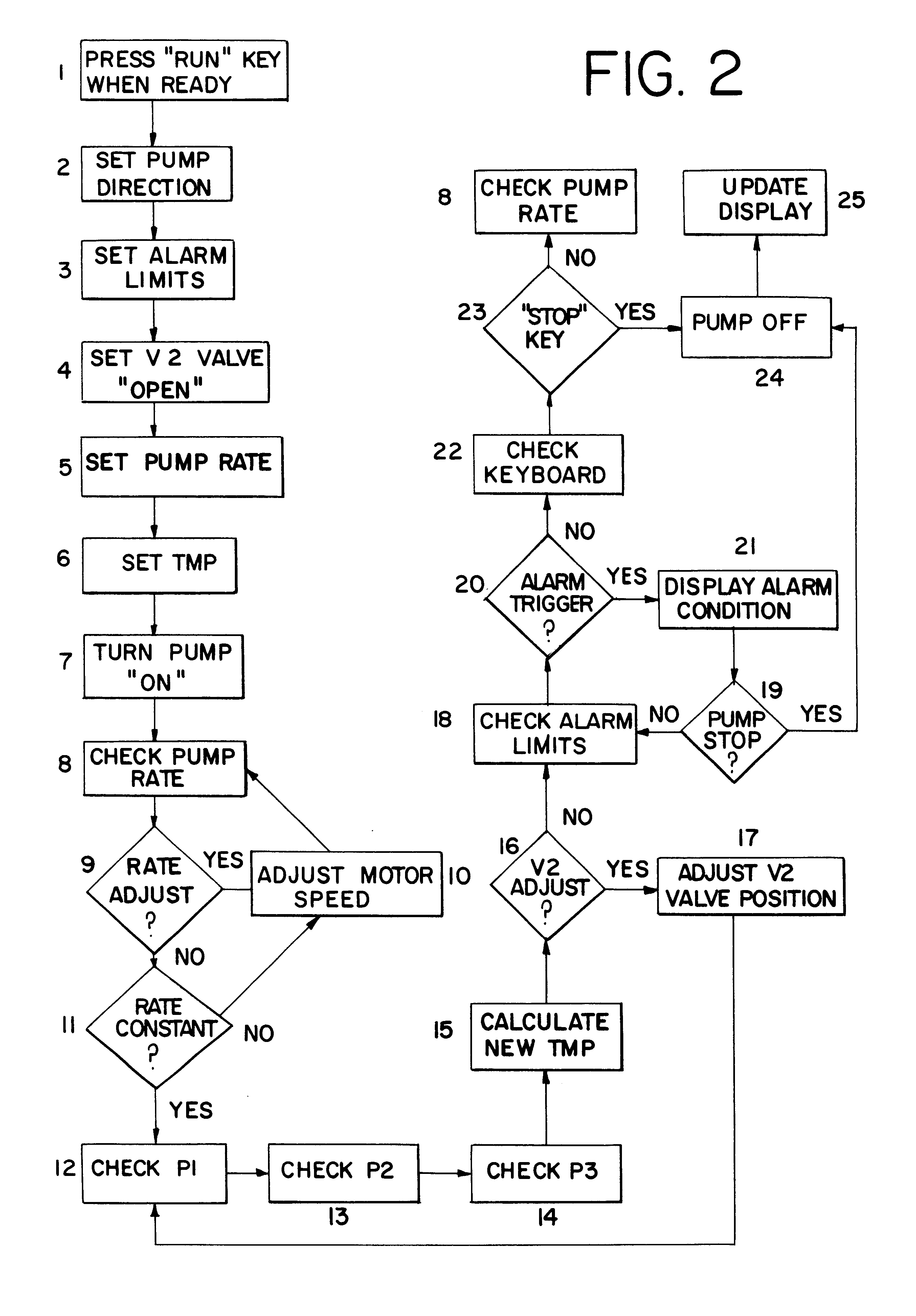
The result is a change in the trans-membrane pressure (TMP) which, if not properly addressed, runs the risk of serious detriment to the operation which incorporates the filtration procedure.
At times, it is not possible to accurately predict the time at which the pumping action must be stopped in order to avoid overtaxing the filter device.
Accordingly, prior art systems which rely solely on timing are not entirely satisfactory.
Prior art filtration technology such as that referred to above also is disadvantageous because it is typically very labor intensive.
One shortcoming is that the filtrate yield is frequently not quantitative because of unpredictable solution particulate loads.
Rapid back pressure build up at times causes bursting of the filter membrane and / or the filter housing, resulting in costly spillage and / or filtrate contamination.
Excessive filter inlet pressure also frequently leads to blow-off of tube connections such as at the filter inlet, resulting in costly spillage of retentate, for example.
Because of these types of shortcomings, manual and semi-automated filtration systems need to be constantly monitored, which greatly contributes to the high labor intensity of such approaches.

Method used


Image

  • Enhancing filtration yields in tangential flow filtration
  • Enhancing filtration yields in tangential flow filtration
  • Enhancing filtration yields in tangential flow filtration

Examples


example 1

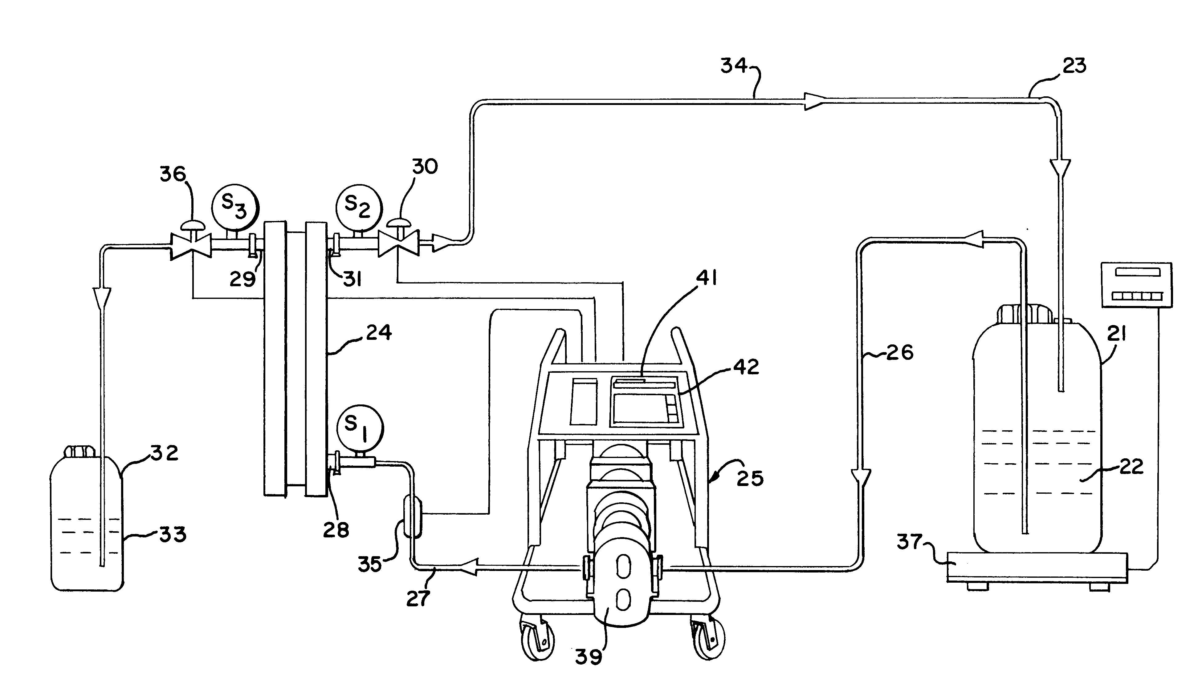
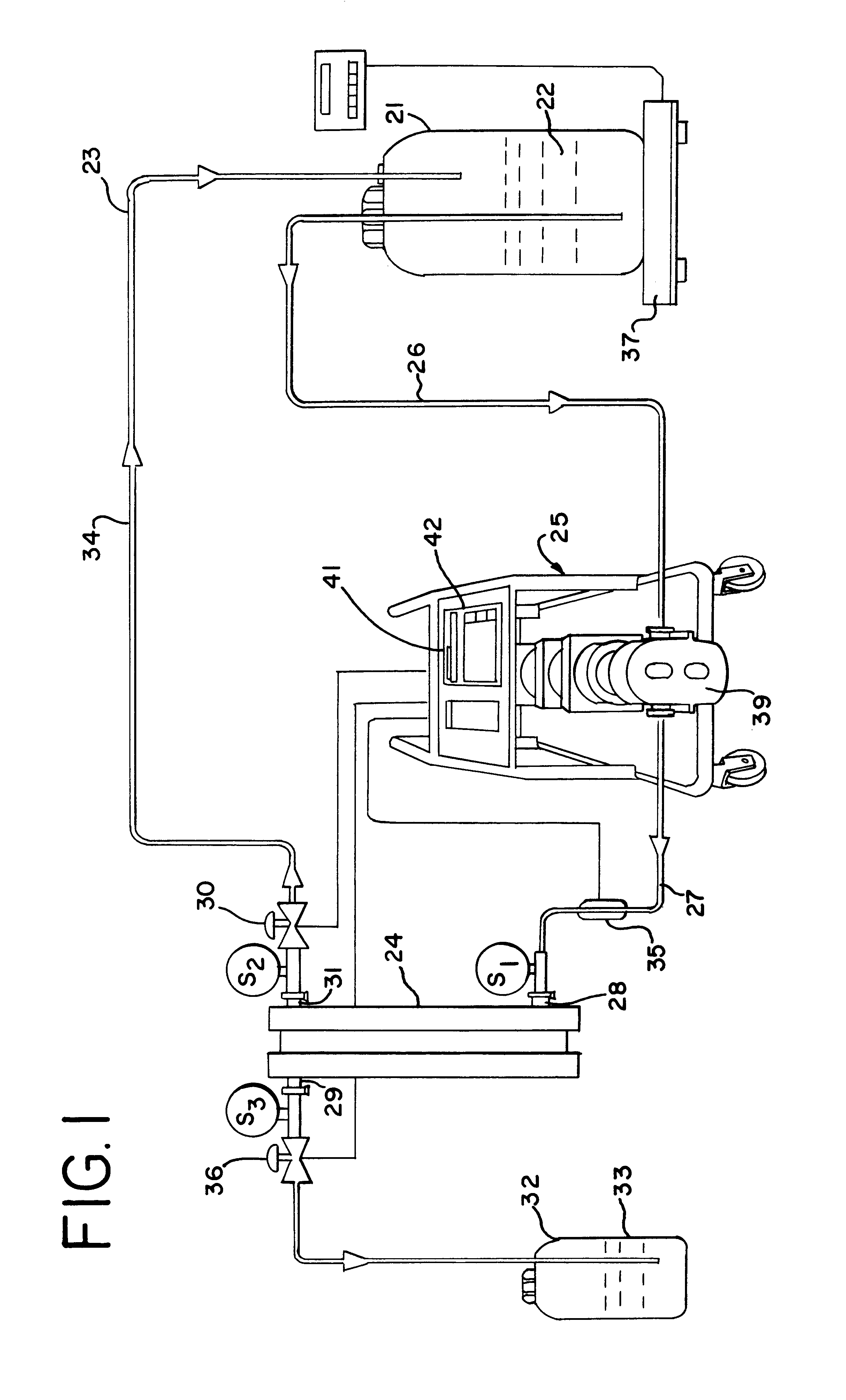
This example illustrates how the system was used to separate extracellular protein (IgG) from a suspension of cells. In this example, a 500 liter suspension of Chinese Hamster Ovary (CHO) cells was the process solution placed within the reservoir 21. The filtration system included a SciPro processor controlled pump unit having a peristaltic pumphead from Cole-Parmar, and an I / P High Precision pumphead. The filtration unit was a Sartocon II cross-flow filtration system available from Sartorius using a 0.45 micrometer Hydrosat cassette. The processor unit was set with the following operating conditions: the cell concentration within the 500 liter batch was 3.times.10 to the 6.sup.th cells / ml. The membrane surface area was 0.6 m.sup.2, with the cross-flow recirculation rate being 12 liters / min using a number 88 Masterflex.TM.. The inlet pressure (P1) was initially 10 psi; the retentate pressure (P2) was initially 5 psi; and the permeate pressure (P3) was initially 2.5 psi, achieved by ...

example 2

The 498 liters of media collected in Example 1 were subjected to a subsequent step of a multi-step separation strategy. The collected media containing the extra-cellular protein (IgG) was concentrated by ultrafiltration within the same type of system. The particular system also included a SciPro processor controlled pump unit of Scilog, Inc., having a Fristam Model 55S lobe pumphead. This system was used to concentrate the dilute protein solution from 498 liters to 2.0 liters, a concentration of approximately 250 times. The filtration system was a Sartocon II cross-flow filtration system using a 20000 MWCO "Ultrasart" cassette. The membrane surface area was 0.7 m.sup.2, the recirculation rate being 17 liters / min. The inlet pressure (P1) was 30 psi, the retentate pressure (P2) was 10 psi, and the permeate pressure (P3) was 0 psi. The trans-membrane pressure was constant at 20 psi during the 4.5 hour processing time.

With this tangential-flow filtration device, the protein remained in ...


PUM

PropertyMeasurementUnit
Pressureaaaaaaaaaa
Flow rateaaaaaaaaaa
Viscosityaaaaaaaaaa

Abstract

A system is provided for proceeding with filtration of liquids in a manner having enhanced control characteristics. Yields are enhanced. The system and method can be used to maintain a substantially constant trans-membrane pressure. When desired, that constant trans-membrane pressure is especially well-suited to yield enhancement for the particular liquid being filtered, concentrated or collected, while minimizing a risk of damage to or loss of valuable components. Additionally, a constant feed rate or pump output can be maintained. Approaches also are described for determining optimal filtration conditions, including trans-membrane pressure and feed rate. Also described is a system and method for determining pressures in a pulsating system with enhanced accuracy by using a peak pressure mode.

Description

BACKGROUND AND DESCRIPTION OF THE INVENTIONThe invention generally relates to the filtration of liquids, more particularly to high precision separation suitable for use in the pharmaceutical and biotechnology industries. The invention is especially applicable to filtration through a porous membrane sheet or a porous hollow fiber column. With the invention, a variety of separation techniques are handled in a yield-enhancing manner and can be automated, including having the separation proceed until a desired level of concentration or other characteristic or parameter is attained. The invention enhances separation processes such as microfiltration, microparticle coating and washing, ultrafiltration, diafiltration and certain preparative chromatography applications. It also improves yield in automated viral infection of mammalian cells such as in gene therapy research and development, as well as rapid cell separation, protein clarification and protein concentration.In the pharmaceutical...

Claims


Application Information

Patent Timeline
IPC IPC(8): B01D61/22B01D61/14B01D61/16
CPCB01D61/145B01D61/16B01D61/22B01D2311/04B01D2315/16B01D2311/14B01D2311/16B01D2313/58B01D61/18
Inventor SCHICK, KARL G.
Owner PARKER INTANGIBLES LLC
Learn More