Luminescent ink for printing of organic luminescent devices

a luminescent device and luminescent ink technology, applied in the field of luminescent ink for printing of organic luminescent devices, to achieve the effects of less energy, high efficiency leds, and promoting the transition of the triplet excited sta

Inactive Publication Date: 2002-04-16
CANON KK
View PDF6 Cites 240 Cited by
  • Summary
  • Abstract
  • Description
  • Claims
  • Application Information

AI Technical Summary

Benefits of technology

To obtain highly efficient LEDs, electronic dopants may be added to the L-ink. The term of dopants is based on conventional silicon semiconductor terminology, wherein a small quantity of dopant can dramatically influence its electrical property. For a L-ink, a small dose of rubrene (red luminescent compound) (less than 5% for instance) addition into Alq.sub.3 (green luminescent compound, more than 94%) can change the material from green light emitter to a red light emitter. This color emission change is caused by the increased energy injected (by electrons and holes) into the Alq.sub.3 (green, hence more energy than red), which is subsequently (energetically) transferred into a lower energy site (here i.e. rubrene, red luminescent material and less energy). Alternatively, some heavy metal porphyrin can be included in the L-ink, like red phosphor 2,3,7,8,12,13,17,18-octaethyl-21H, 23H-porphorine platinum (PtOEP), or green phosphor tris(2-phenylpyridine) iridium [Ir(ppy).sub.3 ] into the L-ink. The addition of such phosphors can promote the transition of triplet excited state to singlet excited state, and thereby increase light-emission efficiency [D. F. O'Brien, et al., Appl. Phys. Lett., 74, 442 (1999)]. The dopant amount is preferably between 0.01 to 15%, preferably between 0.1-8%, and most preferably between 0.5 to 5% by weight.

Problems solved by technology

Many commercial inks are suitable for general printing applications, but not for thin film printing used to fabricate advanced optoelectronic devices.

Method used


Image

  • Luminescent ink for printing of organic luminescent devices
  • Luminescent ink for printing of organic luminescent devices
  • Luminescent ink for printing of organic luminescent devices

Examples


example 1

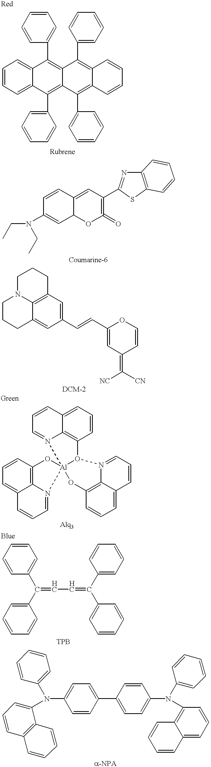
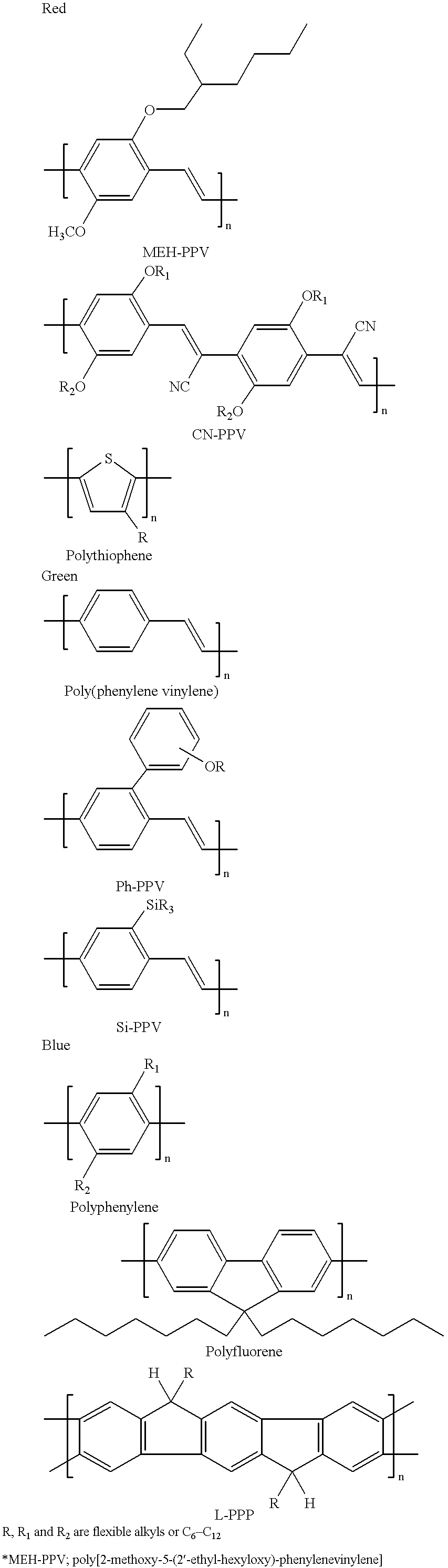
The ink composition gives red fluorescence and is characterized by a peak of 620 nm. The L-ink has a viscosity between 8 and 20 cp. The L-ink prints a thin film having a thickness between about 50 nm to 150 nm. The dry / cure time is about three hours under vacuum at 40.degree. C. The thin film is semi-conductive, with a conductivity below 10.sup.-6 S / cm.

example 2

The ink composition gives green fluorescence. The L-ink has a viscosity between 8 and 20 cp. The L-ink prints a thin film having a thickness between about 50 nm to 150 nm. The dry / cure time is about three hours under vacuum at 40.degree. C. The thin film is semi-conductive, with a conductivity below 10.sup.-6 S / cm.

example 3

The ink composition gives blue fluorescence. The L-ink has a viscosity between 8 and 20 cp. The L-ink prints a thin film having a thickness between about 50 nm to 150 nm. The dry / cure time is about three hours under vacuum at 40.degree. C. The thin film is semi-conductive, with a conductivity below 10.sup.-6 S / cm.


PUM

PropertyMeasurementUnit
boiling pointaaaaaaaaaa
thicknessaaaaaaaaaa
boiling temperatureaaaaaaaaaa

Abstract

Organic luminescent ink (L-ink) is disclosed for use in printing thin films of organic luminescent material. The L-ink is particularly useful in fabricating organic optoelectronic devices, e.g. organic luminescent devices. The L-ink contains at least one organic luminescent material mixed with a solvent and other functional additives to provide the necessary optical, electronic and morphological properties for light-emitting devices (LEDs). The additives play an important role either for enhanced thin film printing or for better performance of the optoelectronic device. The functional additives may be chemically bound to the luminescent compounds or polymers. Luminescent organic compounds, oligomers, or polymers with relatively low solution viscosity, good thin film formability, and good charge transporting properties, are preferred. The L-inks can be cross-linked under certain conditions to enhance thin film properties. The L-ink can be used in various printing methods, such as screen printing, stamp printing, and preferably ink-jet printing (including bubble-jet printing).

Description

The present invention relates generally to luminescent ink compositions, and more particularly, to compositions and methods for printing thin films of organic luminescent material useful in fabricating organic luminescent devices.Printing is a simple and efficient way to create characters, graphics and various patterning on a substrate. Various printing technologies have been developed, such as stamping, screen printing, and ink-jet printing. Ink-jet printing is a non-contact dot-matrix printing technology in which droplets of ink are jetted from a small aperture directly to a specified position on a media. Solidification of the liquid by evaporation of solvent produce patterned thin films with an image. With the advancement of digital technology and the ease of ink control by computer, ink-jet printing process has received great attention in areas where images and information are created and modified digitally. Text and graphics printing are the two most applicable areas for ink-je...

Claims


Application Information

Patent Timeline
Patent Type & Authority Patents(United States)
IPC IPC(8): H01L51/40H01L51/05H01L51/30H01L51/50H01L51/00
CPCH01L51/0005H01L51/0007Y02E10/549H01L51/0034H01L51/0035H01L51/0036H01L51/0037H01L51/0038H01L51/0039H01L51/0042H01L51/0044H01L51/0052H01L51/0059H01L51/0077H01L51/0081H01L51/0084H01L51/0094H01L51/5012Y10S428/917H10K71/135H10K71/15H10K85/10H10K85/111H10K85/1135H10K85/115H10K85/114H10K85/146H10K85/154H10K85/113H10K85/615H10K85/30H10K85/631H10K85/324H10K85/341H10K85/40H10K50/11
Inventor LI, XIAO-CHANG CHARLES
Owner CANON KK
Why Eureka
Try Eureka