It is yet a further object of the present invention to provide such a
system and calibration procedure for a parallel detecting spectroscopic ellipsometer / polarimeter that is performed in three steps, as detailed below, and which minimize the need for recalibration.
The parallel detecting spectroscopic ellipsometer / polarimeter of the present invention provides four combined features into a single
system. These include the analysis of four
channel polarization data using different polarization filters, and / or quarter wave plates, and of a
system for multispectral processing of the four channels. Then, advanced transformation algorithms are used to subject the raw
spectral data to provide specific and detailed analysis, in real-time. In the practice of the present invention, all of these components are assembled into a compact unit that is designed to allow it to be mounted inside of, for example, a thin
film processing chamber. By combining all four of these features into a single compact
package, the parallel detecting spectroscopic ellipsometer / polarimeter of the present invention provides advanced and unique capabilities that no currently known instrument is capable of performing. These capabilities include better than an
order of magnitude decrease in spectroscopic polarization data collection times, as compared to state-of-the-art spectroscopic ellipsometers and true spectroscopic analysis of polarization data at thousands of wavelengths simultaneously, as compared to single wavelength division of amplitude polarimeters. The parallel detecting spectroscopic ellipsometer / polarimeter of the present invention is also of such a design and size that it is capable of being integrated within a standard size thin
film processing chamber. This enables it to be inexpensively adapted for a variety of materials applications, even if the processing chamber in which it is placed had been originally designed without external optical access to the sample. The
sensor system of the present invention is referred to as a parallel detecting, spectroscopic ellipsometer / polarimeter, because it measures the full Stokes vector, that is all four
Stokes parameters, that can be translated into .psi., .
DELTA., intensity, and
depolarization information for thousands of wavelengths. Thus, the instrument is also capable of
polarimetry, of which
ellipsometry is a subset or species.
As noted above, the
sensor system of the present invention provides multispectal wavelength analysis of four
channel polarization data, as compared to existing polarimeters that only measure polarization of a single wavelength at a time, defined, for example by a filter at the
light source or by a
laser source. The multispectral wavelength nature of the parallel detecting spectroscopic ellipsometer / polarimeter sensor system of the present invention required unique design innovations. These include accurate alignment of collected light into four polarization-state channels that deliver the multi-wavelength light into spectrometers, the removal of wavelength dependence of the optical components from the measurement, and the removal of, or the need to calibrate, polarization changes as a function of wavelength from optical components and geometries when making the measurement. This is accomplished in preferred embodiments of the parallel detecting spectroscopic ellipsometer / polarimeter of the present invention in two ways. First, a calibration scheme is provided that removes the polarization and wavelength dependence of the optical components and provides an intensity independent normalization that does not require prior knowledge of the
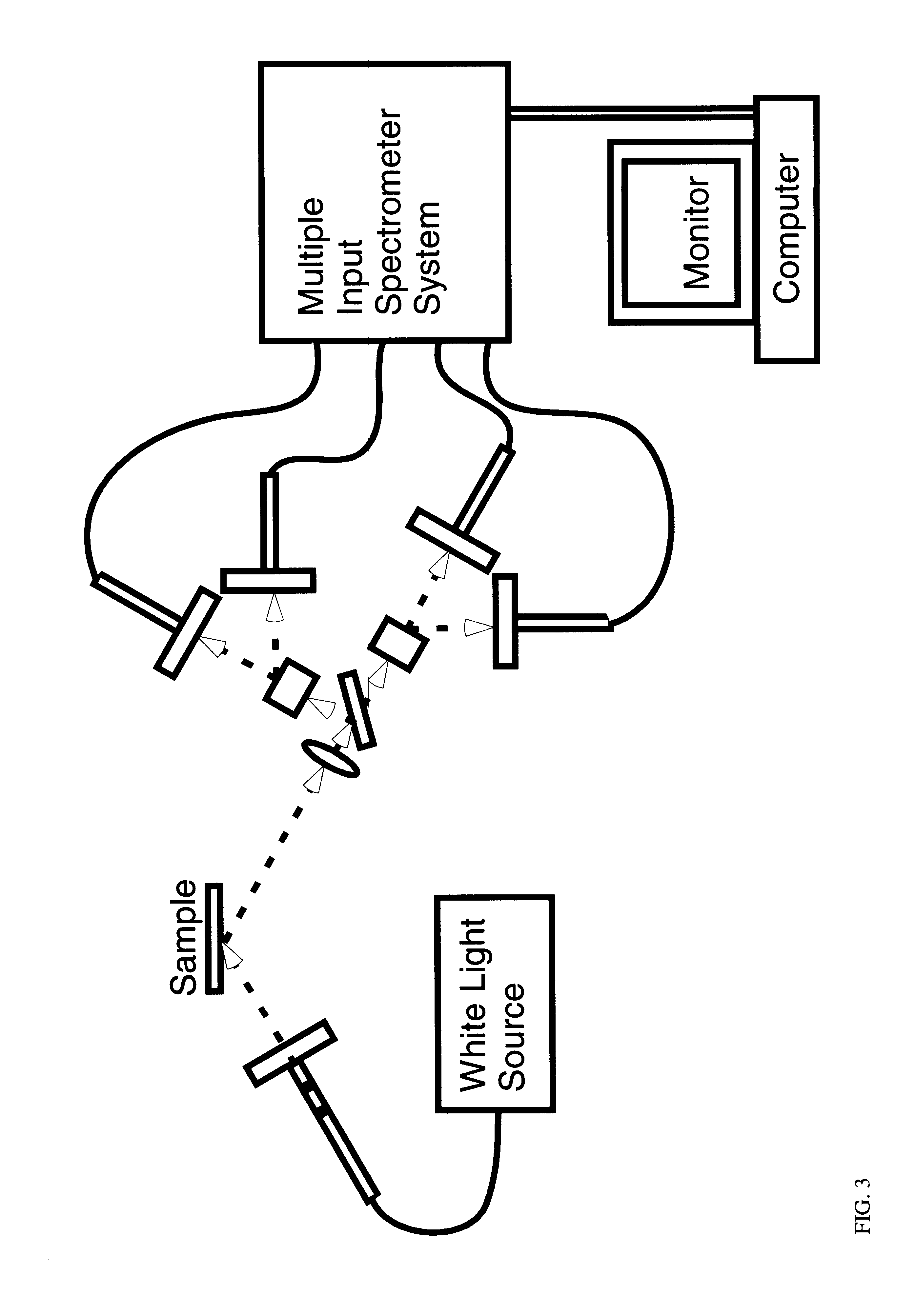
angle of incidence. Then, a mechanism, such as
fiber optic cables coupled through position desensitizing
optics, is used to collect the individually polarized multi-wavelength intensities and deliver them to the spectrometers. While it is possible to place the spectrometers directly with collection
optics, the use of
fiber optics enables the spectrometers, that may be more sensitive to the harsh environments where the polarization measurements are taking place, to be decoupled from the parallel detecting spectroscopic ellipsometer / polarimeter detection head, and therefore removes the requirement for accurate alignment of the spectrometers to the detection optics. This means that, for the first time, polarization measurements with a parallel detecting spectroscopic ellipsometer / polarimeter can be made close to samples in harsh environments, e.g. inside a
vacuum chamber which has significantly elevated temperatures, for example due to
high energy deposition of materials and resulting substrate heating. No currently known polarimeter or ellipsometer provides this flexibility while also providing the complete determination of the optical properties of the sample which is undergoing analysis, as does the parallel detecting spectroscopic ellipsometer / polarimeter of the present invention. All other instruments require an accurately aligned optical window to perform measurements inside a processing chamber. This adaptability and complete characterization capability of the parallel detecting spectroscopic ellipsometer / polarimeter sensor of the present invention enable it to be used for new applications previously not allowed by existing polarimeters and ellipsometers due to their strict geometric and
physical limitations. In addition, the parallel detecting spectroscopic ellipsometer / polarimeter sensor of the present invention can be installed into processing chambers that were originally not designed to accommodate optical monitoring.
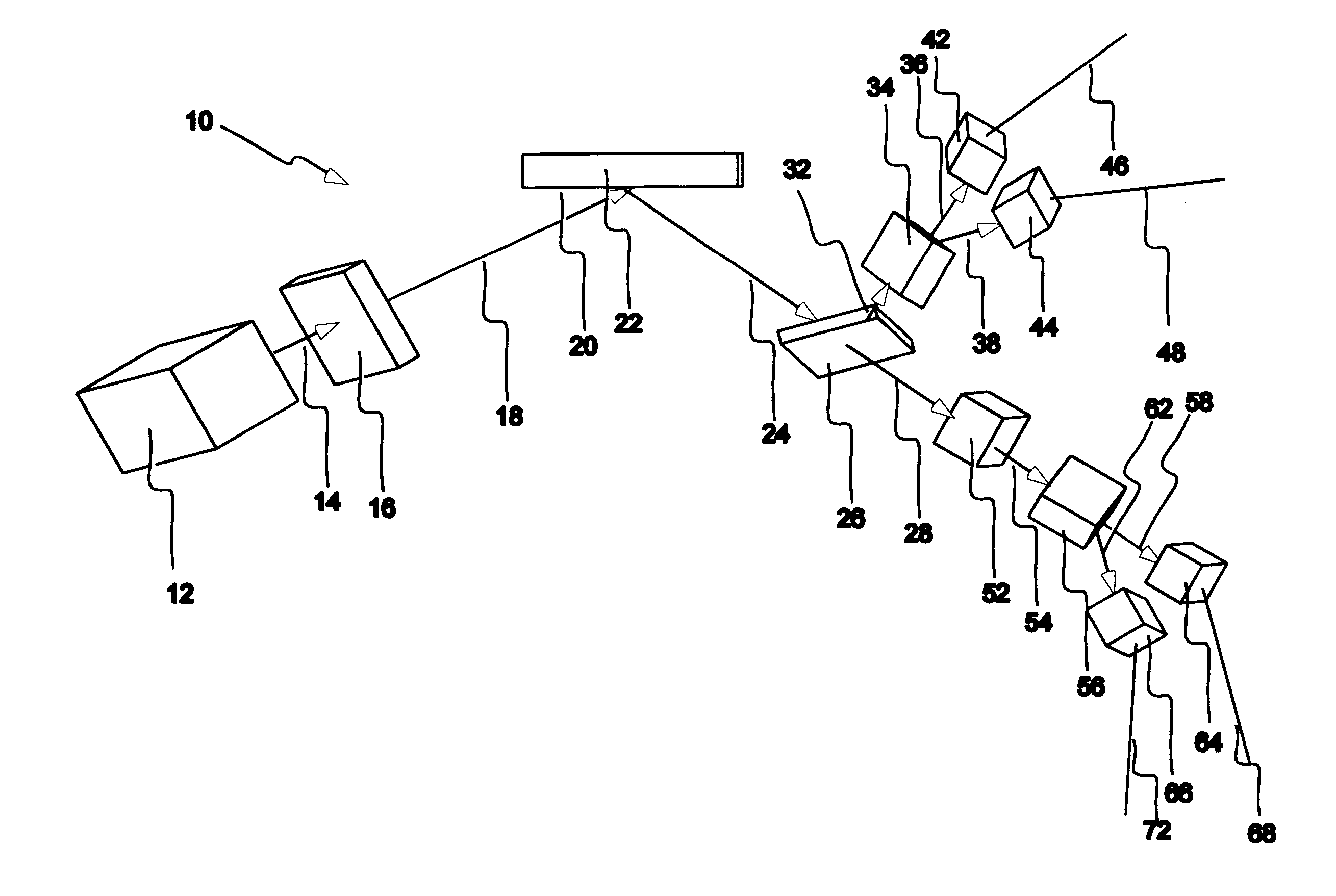
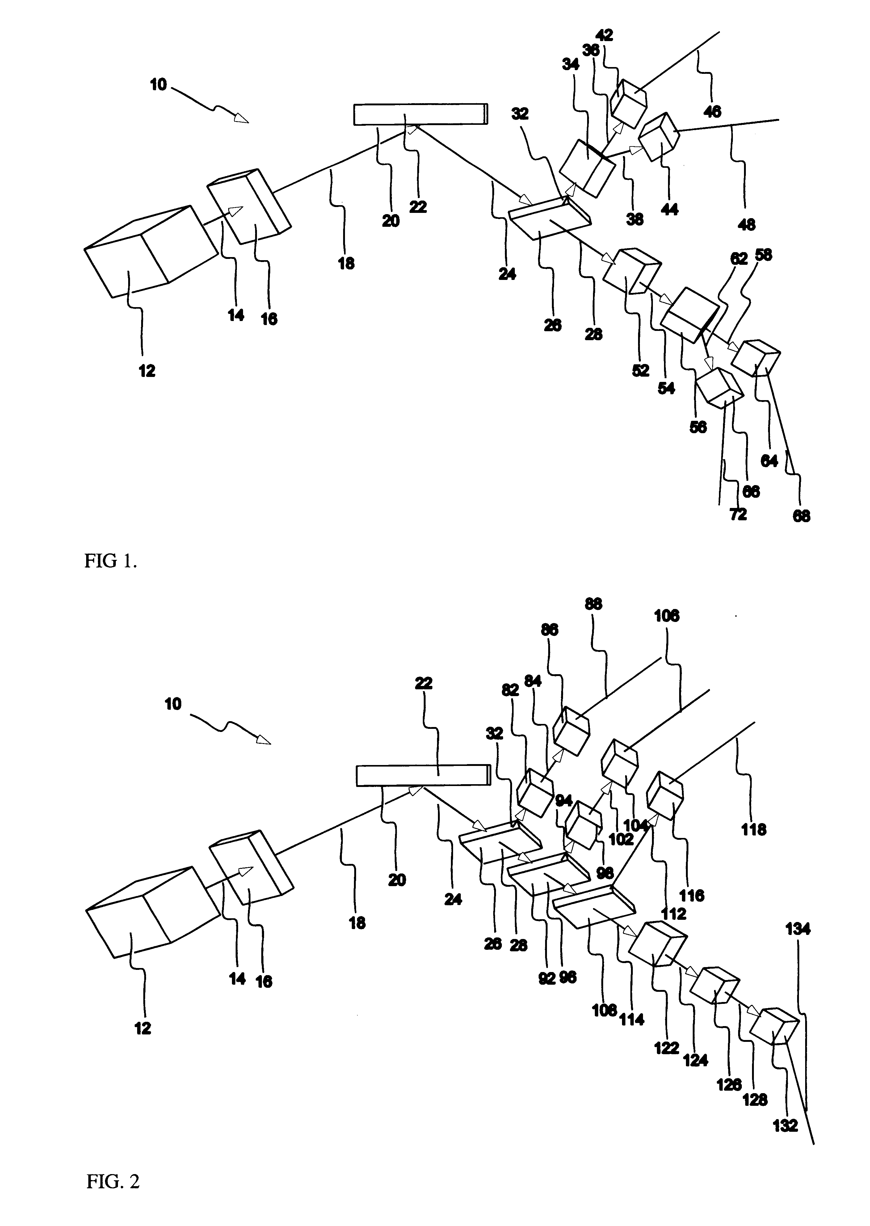
In addition to providing complete measurement of optical properties in a parallel detecting spectroscopic ellipsometer / polarimeter sensor having no
moving parts and in real time, the sensor of the present invention is designed to include a multitude of unique alignment concepts. These include the use of a dual
laser / quadrant
photodiode system that establishes a well-defined geometrical relationship between the sample and the optical heads. This ensures accurate handling of the
optical beam within the head. In addition, CCD (
charge couple device) cameras may be used for alignment of the actual reflected beam. Furthermore, the use of a corner cube and
double reflection from the sample eliminates the need for a source head by combining both the source and detection head into a single unit. This further simplifies the optical access to the sample and makes it possible to adapt the parallel detecting spectroscopic ellipsometer / polarimeter to chambers that may preclude installation within the processing environment. Finally, the use of diffusers, defocusing, and physically larger source beams decrease alignment sensitivity while maintaining
measurement precision and accuracy.
Not only can standard polarimetry, ellipsometry, and
reflectometry information be provided by the parallel detecting spectroscopic ellipsometer / polarimeter of the present invention at multiple incident angles, but additional configurations can be used to obtain additional information. Some of these configurations include replacing the spectral distribution with information delineated according to other characteristics. For example, reference to multiple angle collection of the outgoing light from the sample can be used to perform forward scattering analysis of the surface interaction, thereby providing valuable information about the surface
topography,
grain structure, and other contributions to scattering.
The system may also image an illuminated line on the sample surface onto up to four CCD cameras, thereby detecting the light through up to four polarization-filtered channels. This would yield a spectral
fingerprint of the surface along the line and having spatial resolution that could approach 5 microns. By extending this idea to a general light collector, while giving up the
spectral data, one could obtain a two-dimensional image of the polarization modification characteristics of the sample and therefore perform a broad range of imaging polarimetry measurements. Additional combinations of optics and optical properties integrated directly into the
fiber optics could result in additional
size reduction and
optical path simplification.

