Sputtering method and apparatus for depositing a coating onto substrate

Inactive Publication Date: 2002-07-23
THIN FILMS
View PDF9 Cites 3 Cited by
  • Summary
  • Abstract
  • Description
  • Claims
  • Application Information

AI Technical Summary

Benefits of technology

The object of the present invention is to provide a sputtering deposition method and apparatus for its implementation, as well article of manufacture, comprising substrate and coating, deposited by this method in said appa

Problems solved by technology

Such high temperatures might have number of undesirable consequences, e.g.,
The other disadvantage of the planar diode arrangement is associated with relatively high gas pressure, which should be kept within the diode source chamber, so as to maintain condition for self-sustained glow discharge.
This pressure might affect dispelling of the stream of the target atoms (so-called collision scattering), moving towards the substrate, which in its turn reduces the sputtering rate and prevents the establishing of conditions for formation of homogeneous coating and might even cause deterioration of some properties of the coating.
Reducing of the pressure can, to some extent, decrease the above-mentioned associated negative effects; however, this pressure can not be kept less than a certain minimum, which is 20-100 millibars; otherwise, the density of ions required for sputtering of target atoms falls too rapidly and sputtering rate becomes too slow.
Despite the benefits inherent to the magnetron mode of operation, like relatively low temperatures at the substra

Method used


Image

  • Sputtering method and apparatus for depositing a coating onto substrate
  • Sputtering method and apparatus for depositing a coating onto substrate
  • Sputtering method and apparatus for depositing a coating onto substrate

Examples


example 1

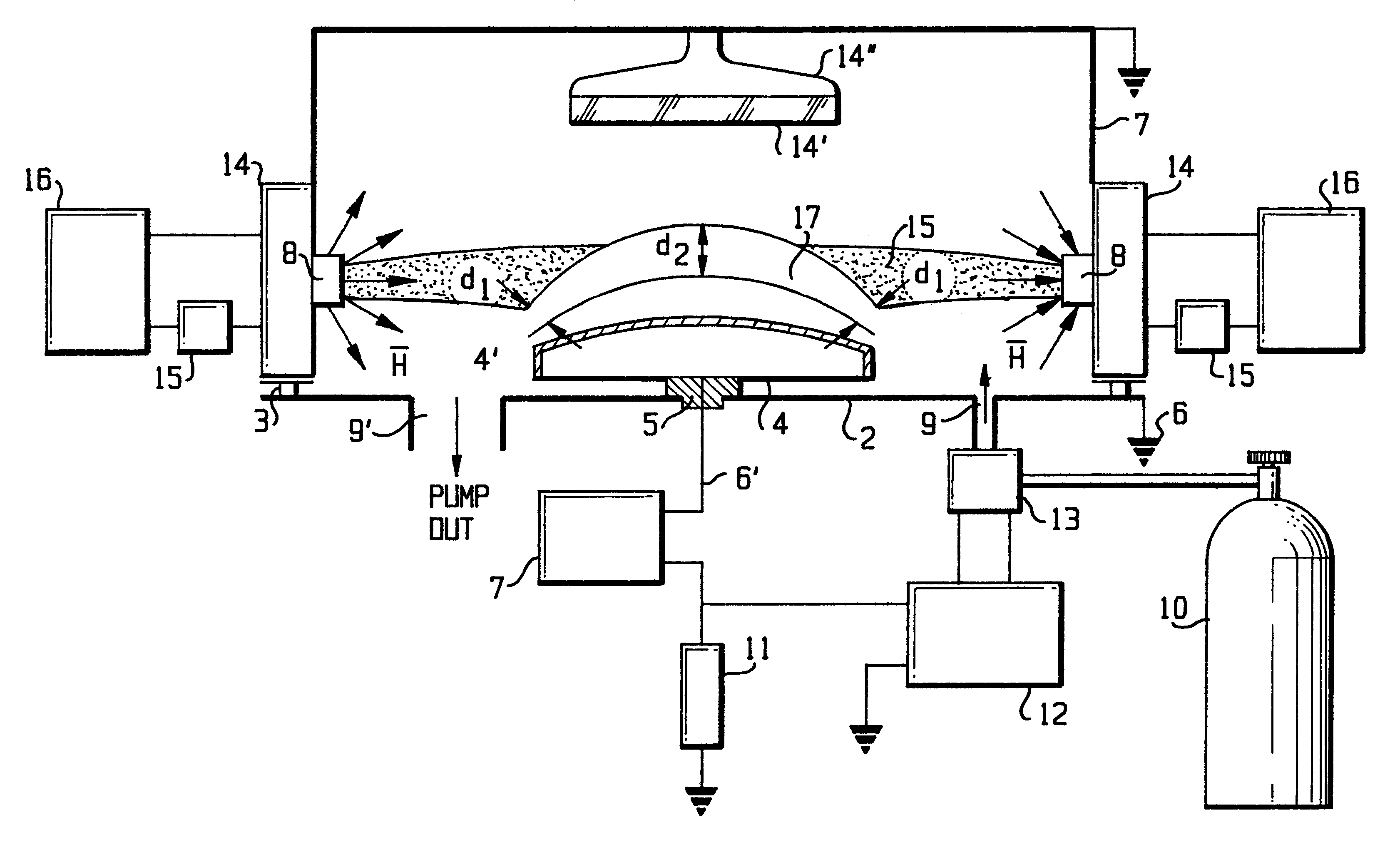
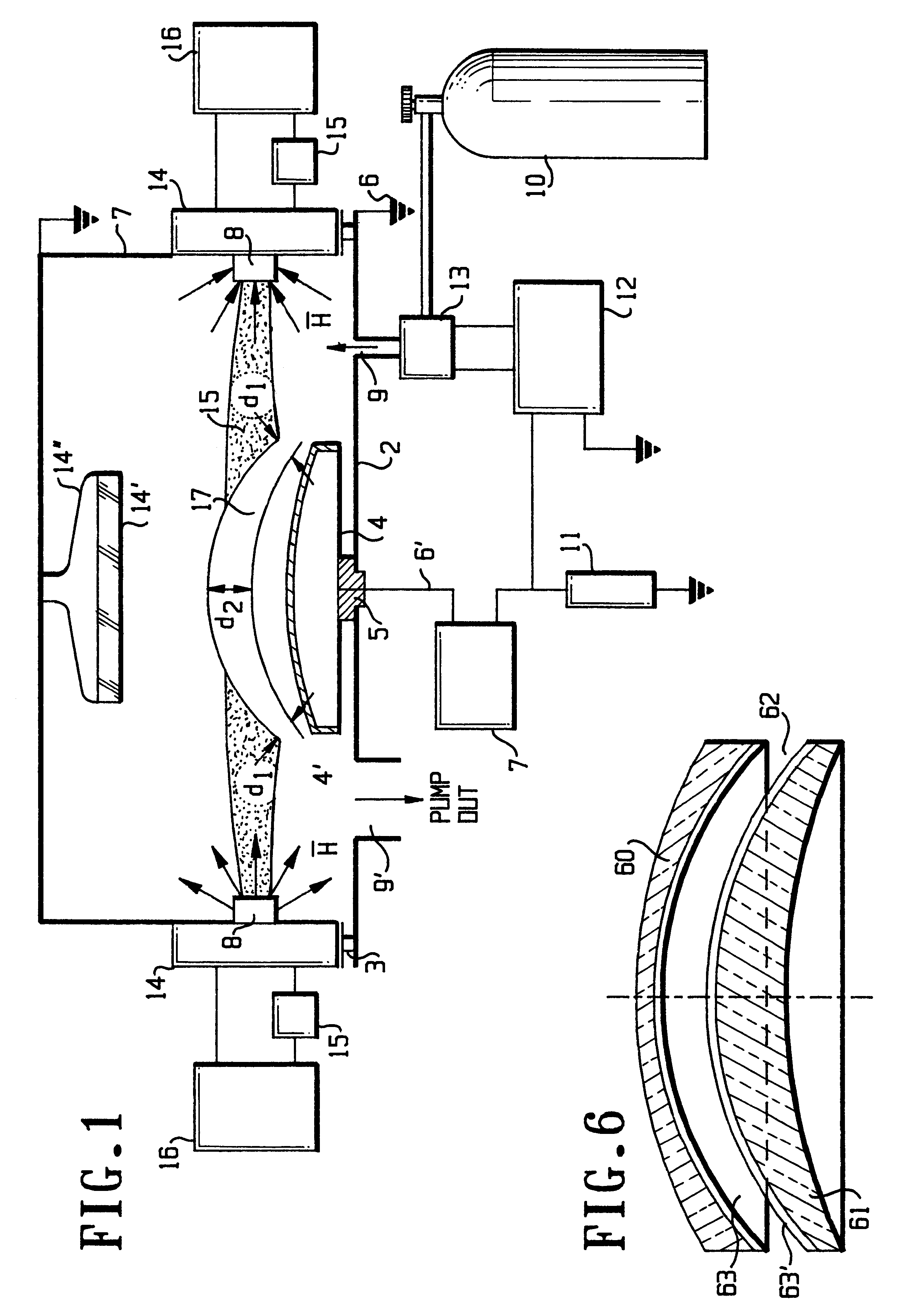
The substrate 14' is mounted on the substrate holding means so as to face the target surface 4' and to be spaced therefrom by a distance 5-20 cm.

The chamber 1 is sealed; its interior is evacuated up to pressure 0.001-0.004 Pa.

The current supply 16 is initiated and parameters of magnetic field are adjusted by means of a control means 15, so as to create a magnetic strength gradient, sufficient for localization of plasma within a region, separated by a distance of 3-15 cm from the substrate 14'.

The power supply 7 is initiated and a potential of 2-5 kV, negative with respect to grounded chamber 1 is supplied to the cathode pole structure 4.

By means of current sensor 11 the value of discharge current is adjusted and the stream of reactive gas mixture is fed into the chamber from the source 10, up to building working pressure, sufficient for maintaining of self-sustained glow discharge. Particular parameters suitable for deposition of Al2O3 coating on stainless steel substrate were:

Suppl...

example 2

Sputtering Conditions:

Water cooled cathode, made of stainless steel, provided with Al target, having square configuration 100.times.300 mm

Anode-cathode distance 60 mm

Reactive gas: mixture of 80% argon with 20% oxygen

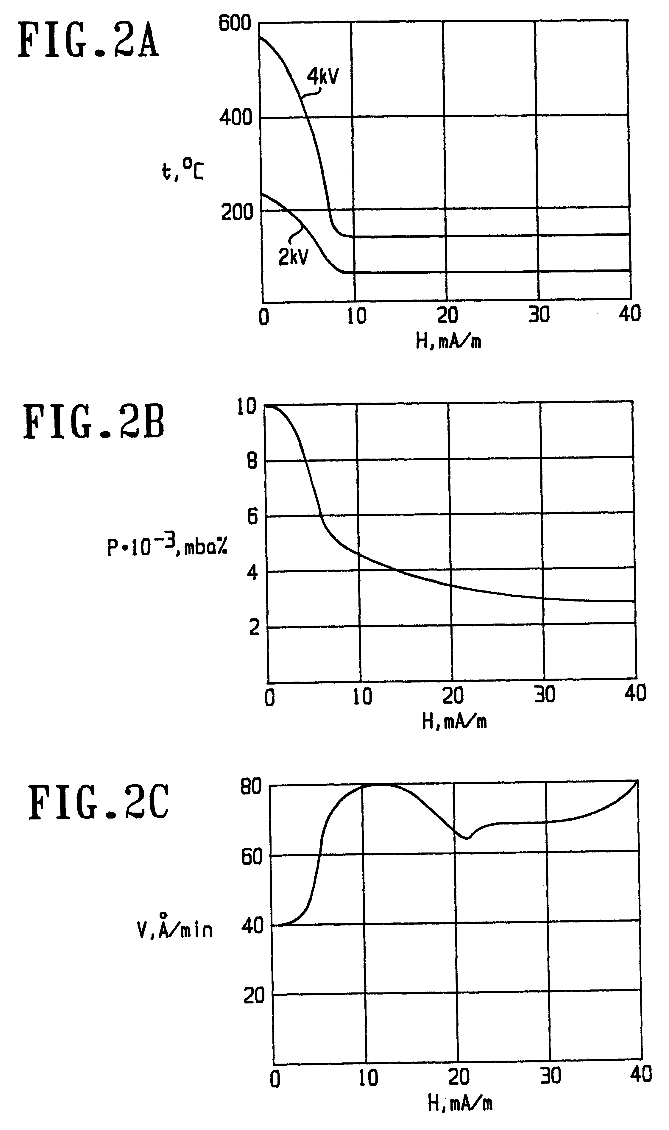
Supplied voltage: 4 kV or 2 kV

Supplied power: 1.2 kW and 0.2 kW respectively

Resulting coating: Alumina

As it can be easily seen in FIG. 2a, sputtering with magnetic focusing is always accompanied by reduction in substrate temperature t and after establishing of magnetic strength H of app. 10 kA / m the temperature has been reduced from 580 / 220 deg.C. down to 130 / 50 deg.C. for supplied voltage 4 / 2 kV respectively.

FIG. 2b shows that when a magnetic field with the strength of at least 10 kA / m is applied in the vicinity of the target surface and the supplied voltage is 4 kV, the working pressure of reactive gas atmosphere reduces from 0,01 mbars (1 Pa) to app. 0.005 mbars (0.5 Pa) without interruption of glow discharge between cathode and anode and termination of sputtering.

FIG...

example 3

Water cooled cathode with diameter 60 mm.

Supplied negative voltage: 2 kV

Discharge current: 300 mA

Reactive gas mixture: 80% Oxygen, 20% Argon

Working pressure: 0,004 mbar

Target material: Si

Substrate material: Kronglass

Magnetic field strength in vicinity of anode: 40 kA / m

Magnetic field strength in vicinity of target surface: 12 kA / m

Resulting coating: SiO.sub.2

For evaluation of chemical resistance the coated and uncoated glass samples were exposed to 80% solution of sulfuric acid at 80 deg.C. for 8 hours and concentration of certain elements was measured before and after exposure within the sample. The uncoated samples were made of Kronglass. A 0.4 .mu.km-thick SiO.sub.2 coating was deposited on both sides of the sample.

Si, Na and K concentrations were measured using the EDS method within the 4 .mu.m-thick surface layer, including the coating.

Table 2 below summarizes the chemical composition of a surface layer, as measured for coated and uncoated samples before and after exposure, as we...


PUM

PropertyMeasurementUnit
Fractionaaaaaaaaaa
Fractionaaaaaaaaaa
Fractionaaaaaaaaaa

Abstract

Sputtering method and apparatus for depositing a coating onto substrate employs variable magnetic field arranged in vicinity of a cathode within a working chamber, filled with ionizable fluid. By controlling a magnetic field topology, i.e. orientation and value of magnetic strength with respect to cathode there is enabled localization and shifting of plasma away from substrate and by thus improvement of adhesion and properties of deposited coatings.

Description

The present invention relates to the coating of substrates by means of physical sputtering effect, in which the transfer of kinetic energy from ions of glow discharge plasma, striking the cathode surface leads to ejection of cathode material from the cathode and to subsequent formation of coating onto the substrate.More particularly, the invention relates to sputtering process carried out in a diode-type apparatus, where glow discharge is established in the working chamber in an atmosphere of ionizable fluid, maintained at reduced pressure between the cathode, constituting a target, and the anode and where cathode atoms, emitted by the bombardment of plasma ions move towards the substrate, mounted in the same chamber.The present invention also refers to articles, provided with the coating, deposited by the sputtering method.The occurrence of a metallic coating which sputtered on the glass walls of a discharge tube was observed in the last century; the explanation for this phenomena ...

Claims


Application Information

Patent Timeline
IPC IPC(8): C23C14/35H01J37/32H01J37/34
CPCC23C14/35H01J37/3402H01J37/3494
Inventor SOROKOV, BORISKHANUKOV, ILYA
Owner THIN FILMS
Why Eureka
Try Eureka