Ultrasonic flow metering system

a flow metering and ultrasonic technology, applied in the direction of instruments, liquid/fluent solid measurement, processing detected response signals, etc., can solve the problems of unfavorable combustion device, unfavorable combustion device, and undesirable contraction of the flow of water through the irrigation pipe, so as to facilitate the triggering of a new pulse and eliminate the sinusoidal nature of the puls

Inactive Publication Date: 2002-12-03
BATTELLE ENERGY ALLIANCE LLC
View PDF39 Cites 162 Cited by
  • Summary
  • Abstract
  • Description
  • Claims
  • Application Information

AI Technical Summary

Benefits of technology

The signal is transmitted to an amplifier 32 in order to overcome the likely extreme attenuation of the broadcast signal that occurs between transmitter 10 and receiver 20.
The amplified signal 33 is then transmitted to a rectifier 34 to substantially eliminate the sinusoidal nature thereof. A rectified signal 35 is then transmitted to an envelope detection circuit 36 that converts rectified signal 35 into a half wave 37. Half wave 37 is then transmitted to a masking or gate circuit. The masking or gate circuit acts as a digital filter. The inventive circuit is configured to expect reception of half wave 37 at digital filter 38 withi

Problems solved by technology

As gas flow meters typically measure a pressure drop such as by using the Venturi principle, the pressure drop may adversely affect the combustion device.
The contraction of the flow of water through an irrigation pipe is undesirable for a number of reasons.
For example, irrigation water often contains debris which can cause an obstruction in a small diameter pipe or which can become caught against a restriction.
An obstruction will result in plugging of the pipe, requiring time, energy, and expense to unplug or otherwise repair it.
In addition, time required to reverse plugging may jeopardize crops which go unwatered during unscheduled down time.
Another problem with differential pressure producing devices is that there is often significant retrofitting required to incorporate them into the system where flow is being measured.
Another problem with measuring flow in a conduit is that variations in temperature and humidity can adversely aff

Method used


Image

  • Ultrasonic flow metering system
  • Ultrasonic flow metering system
  • Ultrasonic flow metering system

Examples


example 15

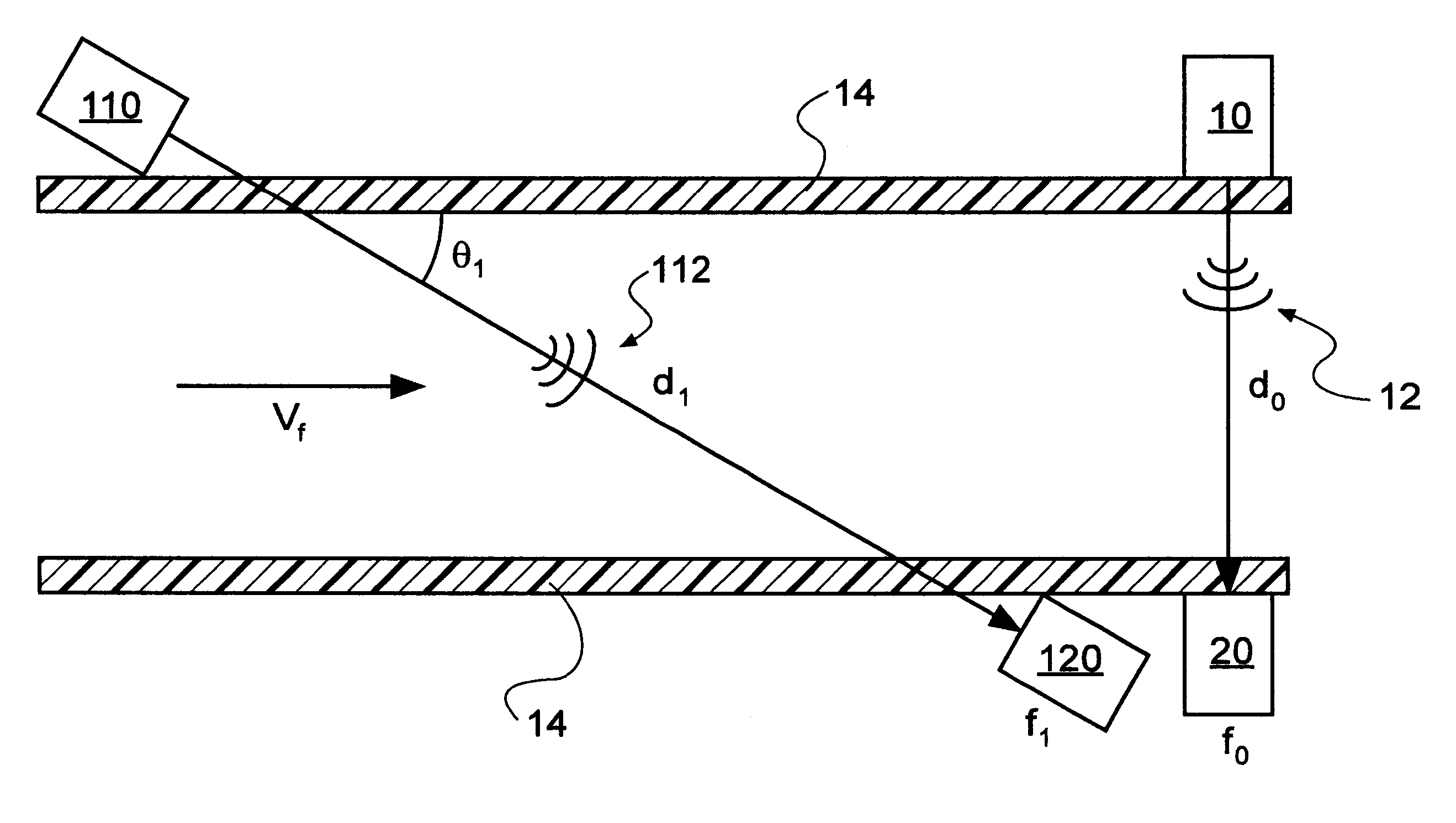
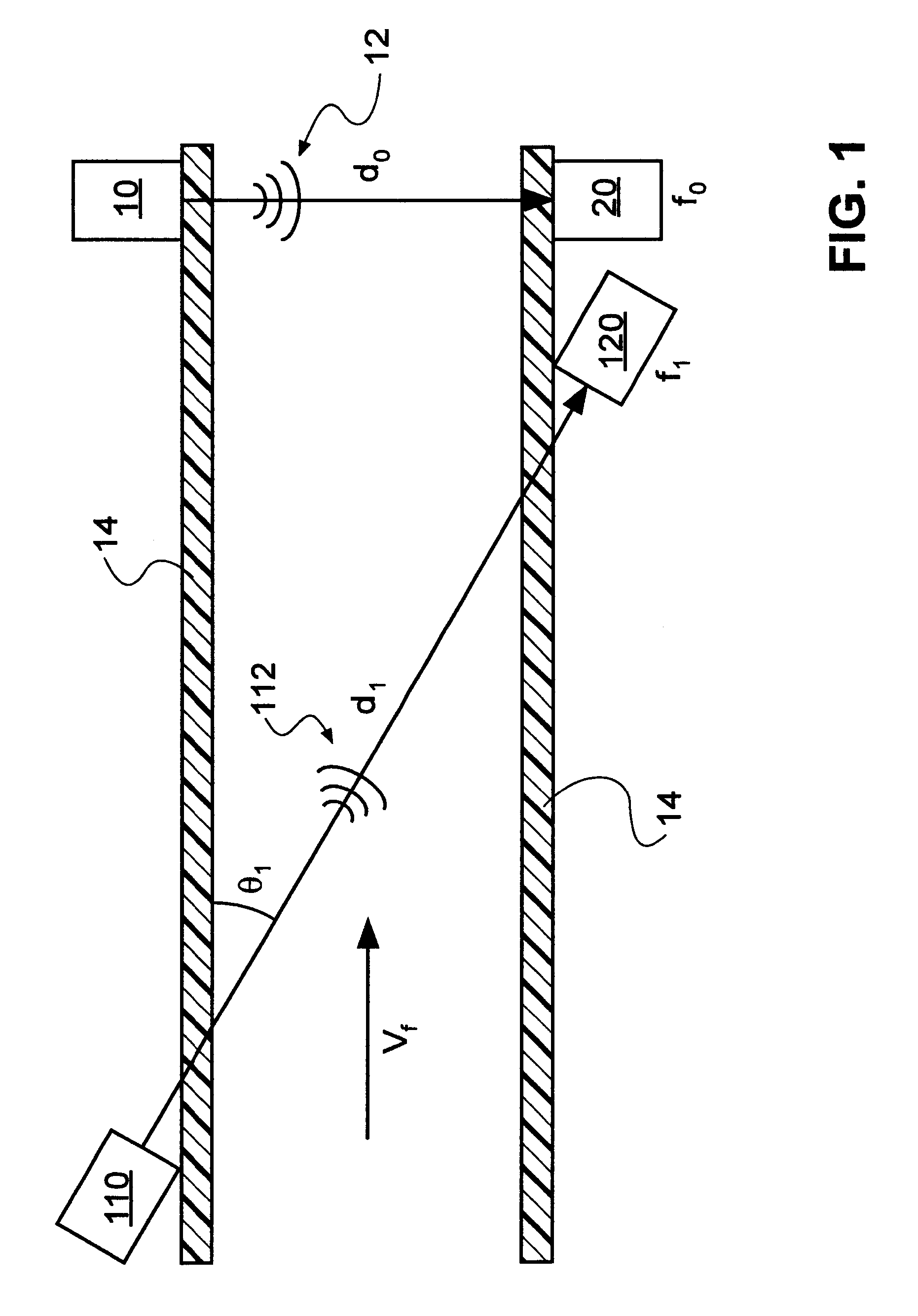
is a paper example of measuring flow velocity of a gas stream past a flat plate. The flat plate is affixed to an aircraft and measurements of flow velocity are taken during a flight. It is assumed that the air stream through which signal 12 and signal 112 pass, is fully developed and boundary layer effects are negligible. Transmitter 10 and receiver 20 are separated by about 3 cm. Transmitter 110 and receiver 120 are separated by about 5 cm. Transmitter 10 and receiver 20 are configured in a substantial vertical arrangement in relation to the flow of air past the flat plate. Transmitter 110 and receiver 120 are configured at an angle that subtends from the horizontal by about 30.degree..

Capacitive coupling effects occur due to both the magnitude of the capacitive charge and the surface areas of transmitters 10, 110 and receivers 20, 120 that are exposed. Transmitters 10, 110 generate a signal in a frequency range between about 100 kHz to about 10 MHz. In this application, where audi...


PUM


Abstract

A system for determining the density, flow velocity, and mass flow of a fluid comprising at least one sing-around circuit that determines the velocity of a signal in the fluid and that is correlatable to a database for the fluid. A system for determining flow velocity uses two of the inventive circuits with directional transmitters and receivers, one of which is set at an angle to the direction of flow that is different from the others.

Description

1. Field of the InventionThe present invention relates to a system for metering flow velocity. More particularly, the present invention relates to a system that measures acoustic pulses in a flowing fluid. In particular, the present invention relates to a velocimeter and a method of comparing acoustic transmission delays between at least two velicometers.2. Relevant TechnologyMany fluid flow applications require real-time evaluation for various reasons such as fluid quality evaluation and process control. Such real-time evaluation allows for dynamic control and monitoring of the fluid flow application. The evaluation of fluid flow in a conduit may be due to the need to control, monitor, or adjust the dynamic volume of fluid being delivered through the conduit. Measuring the flow in a conduit is useful in a number of applications.One such application is measuring the flow of water through an irrigation pipe, particularly in commercial irrigation applications. Flow measurement is usef...

Claims


Application Information

Patent Timeline
IPC IPC(8): G01N29/02G01F1/86G01F1/66G01F1/76G01N29/024G01N29/44
CPCG01F1/667G01F1/86G01N29/024G01N29/4427G01N2291/02818G01N2291/02836G01N2291/056G01N2291/103G01N2291/104
Inventor GOMM, TYLER J.KRAFT, NANCY C.MAUSETH, JASON A.PHELPS, LARRY D.TAYLOR, STEVEN C.
Owner BATTELLE ENERGY ALLIANCE LLC
Why Eureka
Try Eureka