

Method for producing melt-infiltrated ceramic composites using formed supports
a technology of ceramic composites and formed supports, which is applied in the field of ceramic composite production, can solve the problems of inferior products, non-uniform infiltration, and increase the fabrication cost, and achieve the effects of preventing reaction, preventing significant reaction, and superior debonding characteristic of fibers
Inactive Publication Date: 2003-01-07
GENERAL ELECTRIC CO
View PDF18 Cites 170 Cited by
- Summary
- Abstract
- Description
- Claims
- Application Information
AI Technical Summary
Benefits of technology
The mixture can be formed or shaped into a preform or compact by a number of known techniques. For example, it can be extruded, injection molded, die-pressed, isostatically pressed, or slip cast to produce the preform of desired shape and size. Preferably, the preform is of the shape and size of the finished composite article. The present invention generally provides a method of producing the finished composite article having a shape and size that is substantially the same as the shape and size of the preform. Although the Applicants do not wish to be bound by any particular theory, it is believed that the present invention prevents the preform from being distorted during the infiltration of the matrix precursor material when it goes through a weak state before a complete conversion of the matrix precursor to the final ceramic matrix material.
Preferably, the pores in the preform are small, ranging from about 0.1 micron to about 5 microns, and are distributed uniformly throughout the preform, thereby enabling the production of a composite wherein the matrix phase is uniformly distributed through the composite.
The fibers may be advantageously coated with a compound that renders them unreactive toward one or more of the molten precursors of the ceramic matrix materials. In one aspect of the present invention, the fibers are SiC fibers coated with a metal nitride coating, such as boron nitride or silicon-doped boron nitride. The coating prevents a substantial degradation of the fibers when they must be exposed to the molten precursors of the ceramic matrix materials for an extended period of time. Other coatings may be applied to impart a superior debonding characteristic of the fibers in the final composite under severe stress conditions. The metal nitride coating can be deposited by methods well known in the art for depositing a continuous coating without damaging the fiber. Coating processes such as chemical vapor deposition or physical vapor deposition processes, such as sputtering, are suitable. Generally the chemical vapor deposition of metal nitride is carried out at temperatures ranging from about 900.degree. C. to about 1800.degree. C. in a partial vacuum with the particular processing conditions being known in the art or determinable empirically. The metal nitride coating is at least sufficiently thick to be continuous and free of significant porosity. Coating thickness can range from about 0.1 micron to about 5 microns, and typically it is about 1 micron for fibers of about 8 to 15 microns in diameter. The coating thickness should be sufficient to prevent reaction, or prevent significant reaction, between the fibers and the infiltrating precursors of the ceramic matrix materials under the particular processing conditions used. In the case of a composite of SiC fibers in a SiC matrix, the precursor of the ceramic matrix material is typically silicon. During the infiltration process, the metal nitride coating may or may not react with or dissolve in the molten silicon depending on the time and temperature; i.e., the metal nitride coating will survive better at lower temperatures and for shorter times of infiltration. Generally, silicon infiltration time increases with the size of the preform. Therefore, larger-sized preforms may require thicker nitride coatings. The present invention advantageously limits the required time of exposure of the fiber preform to molten silicon and still provides a substantially uniform composition of the ceramic composite article.
The outer coating of the fibers can promote wetting to improve the infiltration by capillarity, provide a desirable debonding with the matrix, or reduce the reaction between the matrix and the fiber during high temperature service. Moreover, the fibers may also be coated with a material that renders them readily wettable by the molten precursor of the ceramic matrix material.
Infiltration is performed at greater than or equal to the melting point of the precursor of the ceramic matrix material. In the case of silicon, the infiltration temperature is in a range from about 1400.degree. C. to about 1600.degree. C., preferably from about 1415.degree. C. to about 1500.degree. C., more preferably from about 1425.degree. C. to about 1450.degree. C. Higher temperatures lower the viscosity of molten silicon and promotes a better diffusion of the molten silicon into the fiber preform, but they can unnecessarily accelerate a degradation of the fibers. Although the Applicants do no wish to be bound by any particular theory, it is believed that the present invention promotes a diffusion of a molten precursor of the ceramic matrix material from both outer and inner surfaces of the fiber preform and / or allows for the escape of any gaseous product of the infiltration process. Thus, the time required for a complete infiltration can be substantially reduced, and thereby, reducing the chance that the fibers may be damaged, and at the same time a more uniform infiltration results.
Problems solved by technology
This can result in nonuniform infiltration characterized by incompletely filled areas and, thus, an inferior product.
Although post-infiltration machining of this excess metal can be undertaken, it not only increases the fabrication cost but also can accidentally expose some of the fibers and provide points for environmental attack.
Third, during the liquid-phase infiltration, especially with molten silicon, the shaped body typically passes through a relatively weak state (following burn-out of the temporary binder but before a complete infiltration and reaction of the matrix material) which can easily yield a distorted finished shape.
Method used
View moreImage
Smart ImageViewing Examples

Examples
example 2
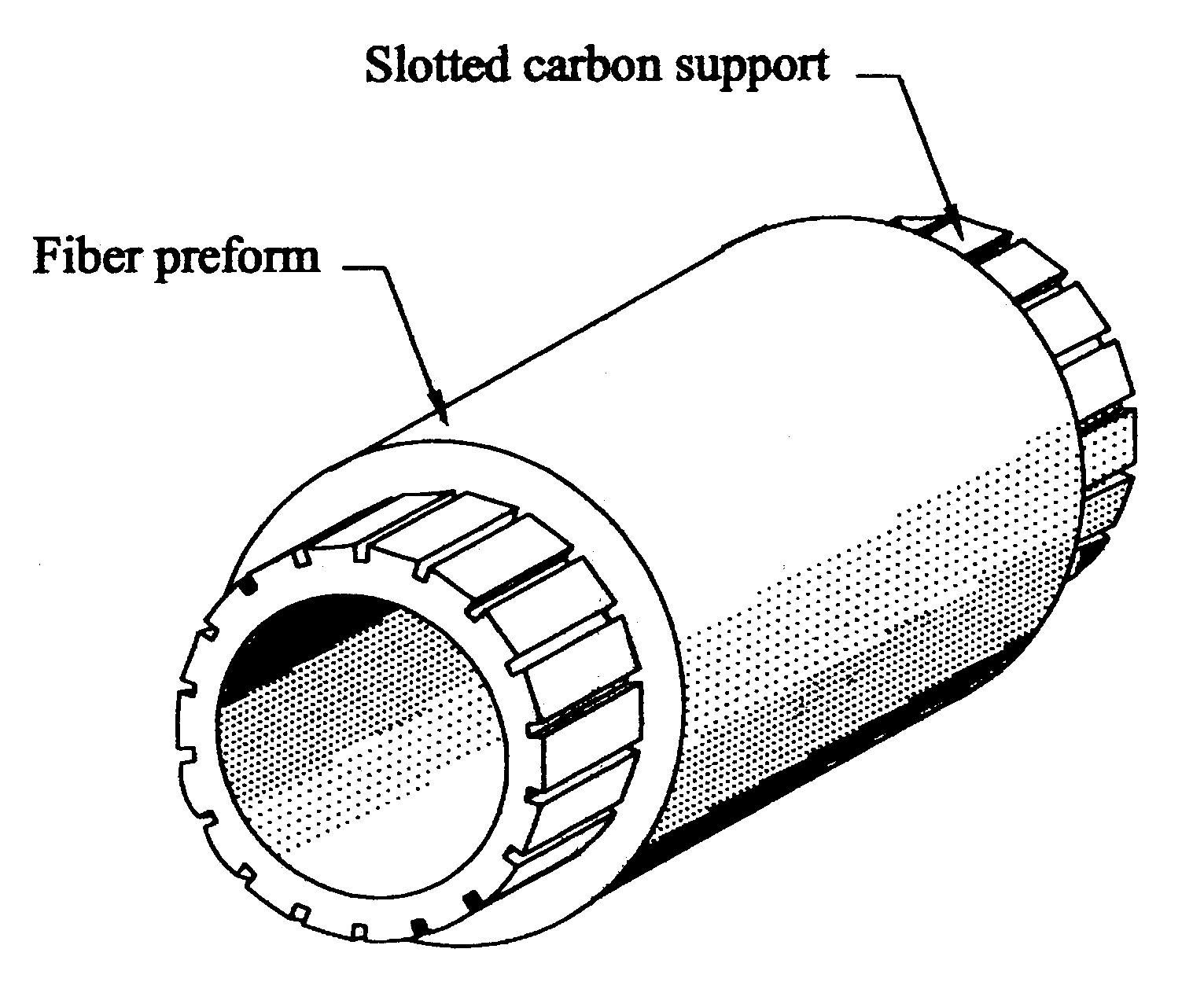
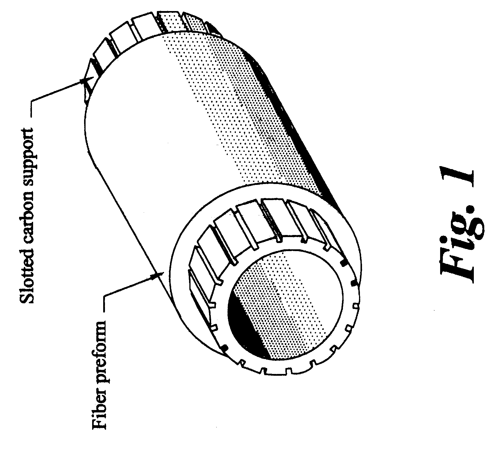
Several shroud rings of composite material of SiC fibers in SiC matrix having an ID of 46.61 cm were fabricated using the procedure of Example 1 and a slotted carbon mandrel. Shroud rings require a very tight tolerance on the ID dimension and the circularity. By fabricating the shroud rings on the carbon mandrel, the required tolerance of 0.5 mm was achieved, as measured by a coordinate measuring machine. In contrast, smaller shrouds made without a supporting mandrel showed out-of-roundness values of up to about 6 mm. These results indicated that dimensional tolerance was consistently achieved with the present invention.
Login to View More PUM
| Property | Measurement | Unit |
|---|---|---|
| width | aaaaa | aaaaa |
| width | aaaaa | aaaaa |
| temperature | aaaaa | aaaaa |
Abstract
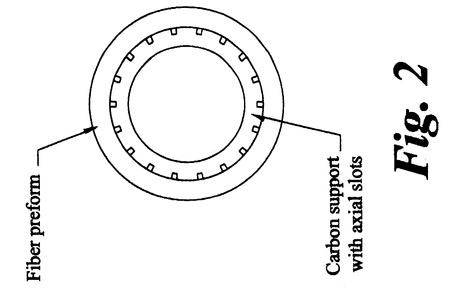
A method for producing shaped articles of ceramic composites provides a high degree of dimensional tolerance to these articles. A fiber preform is disposed on a surface of a stable formed support, a surface of which is formed with a plurality of indentations, such as grooves, slots, or channels. Precursors of ceramic matrix materials are provided to the fiber preform to infiltrate from both sides of the fiber preform. The infiltration is conducted under vacuum at a temperature not much greater than a melting point of the precursors. The melt-infiltrated composite article substantially retains its dimension and shape throughout the fabrication process.
Description
BACKGROUND OF INVENTIONThe present invention relates to a method for producing a ceramic composite. In particular, the present invention relates to melt-infiltrated ceramic composites and to a method for producing the same.U.S. Pat. Nos. 4,120731; 4,141,948; 4,148,89; 4,220,455; 4,238,433; 4,240,835; 4,242,106; 4,247,304; 4,353,953; 4,626,516; 4,889,686; and 4,944,904; assigned to the assignee hereof and incorporated herein by reference, disclose molten silicon infiltration of materials which include carbon, molybdenum, carbon-coated diamond, cubic boron nitride, and blends of carbon with silicon carbide, boron nitride, silicon nitride, aluminum oxide, magnesium oxide and zirconium oxide.Reinforced ceramic matrix composites ("CMCs") comprising micron-sized fibers having one composition, which fibers are dispersed in continuous ceramic matrices of the same or different composition, are well suited for structural applications because of their toughness, thermal resistance, high-temper...
Claims
Login to View More Application Information
Patent Timeline
 Patent Type & AuthorityPatents(United States)
IPC IPC(8): C04B35/63C04B35/636C04B35/80C04B35/634C04B35/52C04B35/573C04B35/565C04B35/563C04B35/84
CPCB32B18/00C04B35/563C04B35/573C04B35/62863C04B35/62868C04B35/62873C04B35/634C04B35/636C04B35/76C04B35/806C04B35/653C04B35/52C04B2237/64C04B2235/3826C04B2235/386C04B2235/42C04B2235/422C04B2235/428C04B2235/524C04B2235/5244C04B2235/5248C04B2235/5252C04B2235/526C04B2235/5264C04B2235/94C04B2237/704C04B2235/656C04B2235/6567C04B2235/6581C04B2235/661C04B2237/30C04B2237/36C04B2237/361C04B2237/363C04B2237/365C04B2237/366C04B2237/38C04B2237/60C04B2237/62C04B35/80
InventorCORMAN, GREGORY SCOTBRUN, MILIVOJ KONSTANTINMCGUIGAN, HENRY CHARLES
OwnerGENERAL ELECTRIC CO