

Electrolytic capacitor, circuit board containing electrolytic capacitor, and method for producing the same
a technology of electrolytic capacitors and circuit boards, applied in the direction of electrolytic capacitors, liquid electrolytic capacitors, printed circuit non-printed electric components associations, etc., can solve the problems of difficult to obtain an esl value lower than 1 nh in the conventional specialty polymer electrolytic capacitor, esr inferior to a multi-layer ceramic capacitor, and hardly reduced esl
- Summary
- Abstract
- Description
- Claims
- Application Information
AI Technical Summary
Problems solved by technology
Method used
Image

Examples
example 1
An electrolytic capacitor according to the first embodiment was produced.
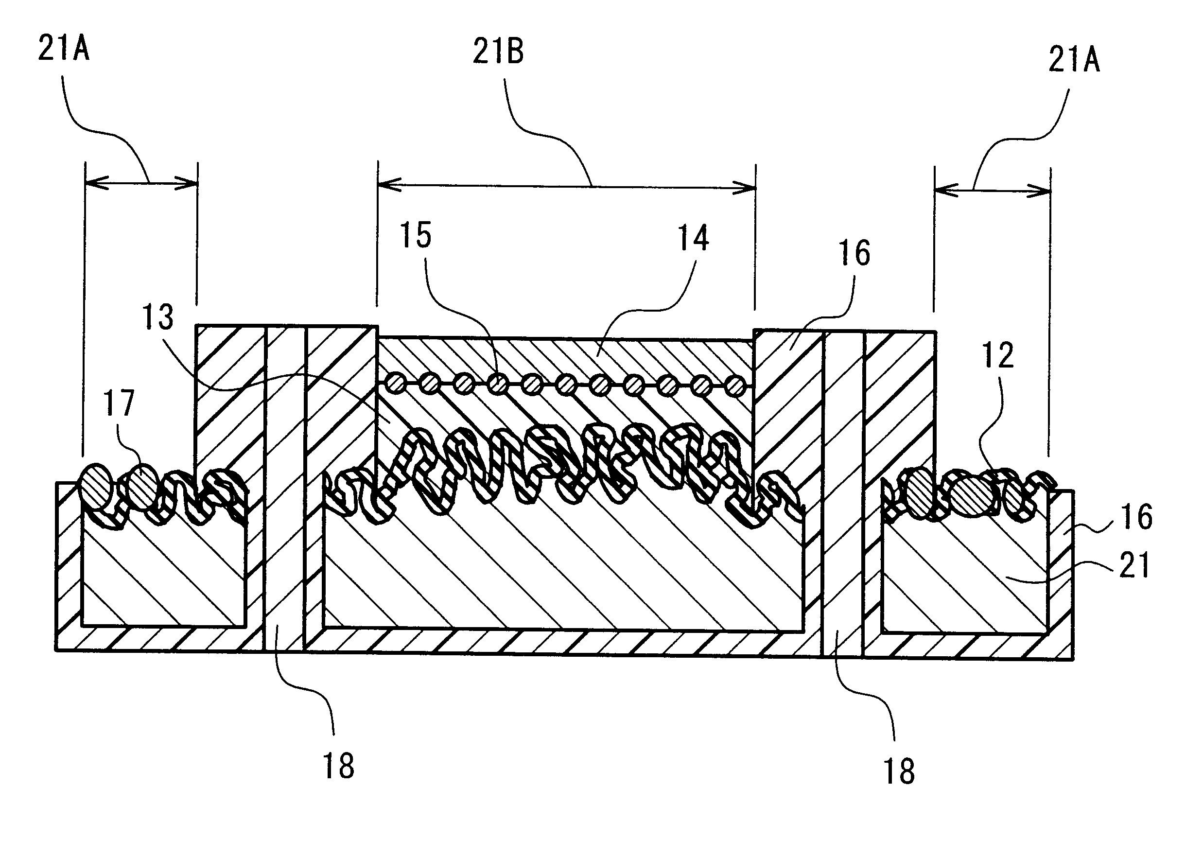
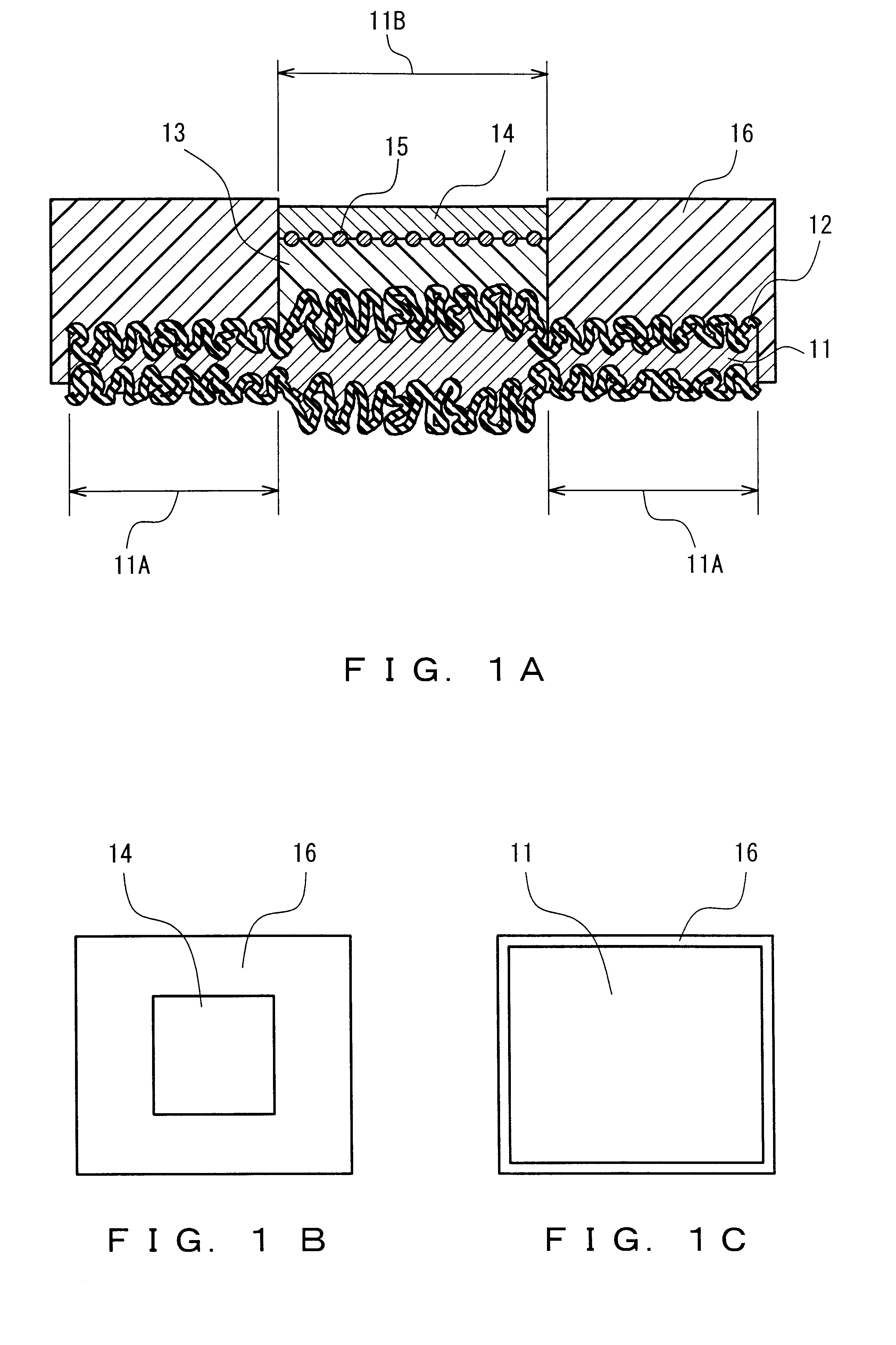
An aluminum foil with a purity of 99.99% and a thickness of 100 .mu.m, used as the anode-use valve metal foil 11, was subjected to electrolytic etching in an electrolytic solution containing hydrochloric acid mainly at a concentration of 10 wt % at a liquid temperature of 35.degree. C., with an alternating current applied thereto, so that the aluminum foil had a rough surface. The rough surface layer thus formed was 40 .mu.m thick.
Subsequently, the capacitor forming part 11B of the anode-use valve metal foil 11 was pressed by a plate press machine so that the rough surface layer thereof was compressed to a compression level of 0.8.
Next, the electrode lead part 11A was pressed by a plate press machine so that the rough surface layer thereof was compressed to a compression level of 0.4.
Next, the anode-use valve metal foil 11 was subjected to constant voltage forming at a forming voltage of 8 V in a 5 wt % ammoniu...
example 2
An electrolytic capacitor according to the second embodiment was produced.
An aluminum foil with a purity of 99.99% and a thickness of 100 .mu.m, used as the anode-use valve metal foil 11, was subjected to electrolytic etching in an electrolytic solution containing hydrochloric acid mainly at a concentration of 10 wt % at a liquid temperature of 35.degree. C., with an alternating current applied thereto, so that the aluminum foil had a rough surface. The rough surface layer thus formed was 40 .mu.m thick.
Subsequently, the capacitor forming part 11B of the anode-use valve metal foil 11 was pressed by a plate press machine so that the rough surface layer thereof was compressed to a compression level of 0.5.
Next, the anode-use valve metal foil 11 was subjected to constant voltage forming at a forming voltage of 8 V in a 5 wt % ammonium adipate aqueous solution at a liquid temperature of 60.degree. C. as an anodic oxidation solution, so that the dielectric layer 12 was formed on surfaces...
example 3
An electrolytic capacitor according to the fifth embodiment was produced.
An aluminum foil with a purity of 99.99% and a thickness of 100 .mu.m, used as the anode-use valve metal foil 31, was subjected to electrolytic etching in an electrolytic solution containing hydrochloric acid mainly at a concentration of 10 wt % at a liquid temperature of 35.degree. C., with an alternating current applied thereto, so that the aluminum foil had a rough surface. The rough surface layer thus formed was 40 .mu.m thick.
Subsequently, the capacitor forming part 31B of the anode-use valve metal foil 31 was pressed by a plate press machine so that the rough surface layer thereof was compressed to a compression level of 0.8.
Next, the electrode lead part 31A was pressed by a plate press machine so that the rough surface layer thereof was compressed to a compression level of 0.4.
Next, the anode-use valve metal foil 31 was subjected to constant voltage forming at a forming voltage of 8 V in a 5 wt % ammoniu...
PUM
| Property | Measurement | Unit |
|---|---|---|
| thickness | aaaaa | aaaaa |
| thickness | aaaaa | aaaaa |
| thick | aaaaa | aaaaa |
Abstract
Description
Claims
Application Information