
Measuring chip for surface plasmon resonance biosensor and method for producing the same

a surface plasmon and biosensor technology, applied in the direction of liquid gas reaction, gas-gas reaction process, instruments, etc., can solve the problems of insufficient detection of inability to detect surface plasmon phenomena of the medium, and inability to use conventional methods

Inactive Publication Date: 2003-09-30
DAI NIPPON PRINTING CO LTD +1
View PDF5 Cites 54 Cited by
  • Summary
  • Abstract
  • Description
  • Claims
  • Application Information

AI Technical Summary

Benefits of technology

Another objective of the present invention is to provide a measuring cell for a surface plasmon resonance sensor that can detect a small amount of target substances in high sensitivity.

Problems solved by technology

Conventional methods are known to be intricate and require labeling substances.
However, this method has a disadvantage in that LB membrane binds poorly to a metal thin-film and peels off together with the physiologically active substance.
If the thickness exceeds 3,000 angstroms, surface plasmon phenomena of the medium cannot be sufficiently detected.
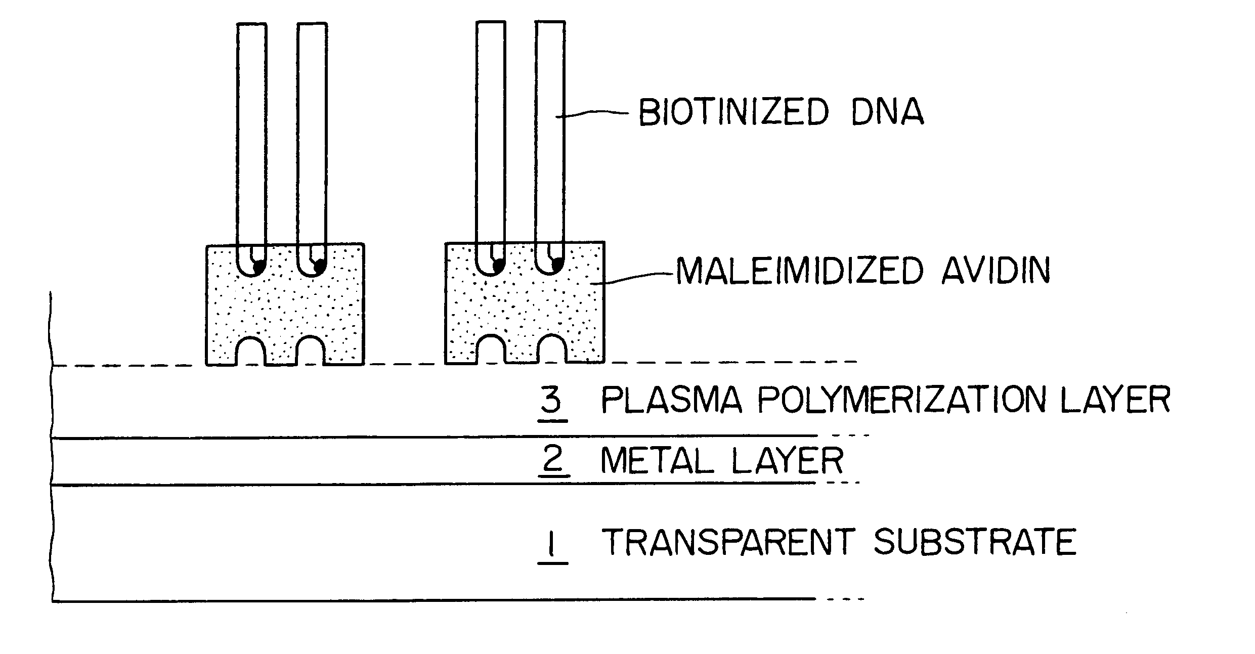
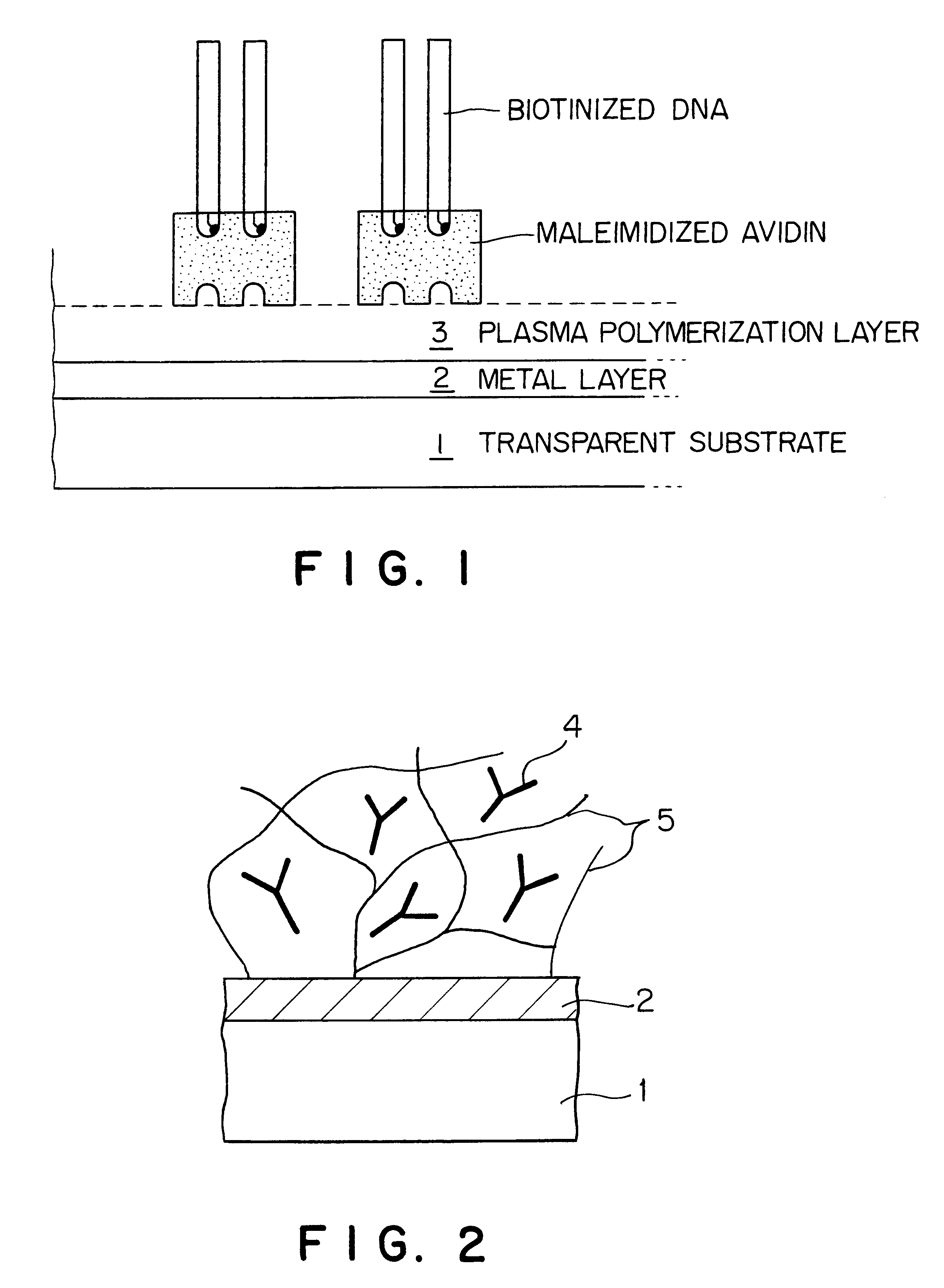
First, metal thin-film 2 is formed on transparent substrate 1. Metal thin-film 2 can be formed by conventional methods such as sputtering, CVD, PVD, or vacuum evaporation.
Second, plasma polymerization layer 3 is formed on metal thin-film 2. Plasmapolymerization layer 3 can be formed by plasma polymerization using a plasma polymerization apparatus. The rate of plasma formation is preferably 100 to 3000 angstroms / min, most preferably 500 to 1000 angstroms / min. If the rate exceeds 3000 angstroms / min, it becomes difficult to obtain a smooth plasma polymerization layer. More specifically, the plasma polymerization can be preferably carried out at a monomer material flow rate of 0.05 to 100 sccm at a room temperature or at a temperature of 10 to 20C. at a pressure between 1.0.times.10.sup.-2 and 1.0.times.10.sup.2 Pa using a discharge power of 20 to 300 W at a discharge frequency of 10 MHz or 13.56 MHz. However, polymerization conditions are not restricted to the conditions above.

Method used


Image

  • Measuring chip for surface plasmon resonance biosensor and method for producing the same
  • Measuring chip for surface plasmon resonance biosensor and method for producing the same
  • Measuring chip for surface plasmon resonance biosensor and method for producing the same

Examples


example 1

A measuring chip having layers shown in FIG. 1 on an optical recognition part was constructed.

A glass plate with a thickness of 0.15 mm (18 mm.times.18 mm) was used for a transparent substrate. A chrome layer and then a gold layer were deposited on this transparent substrate by sputtering. The sputtering was carried out at 100 W for 40 seconds for the chrome layer and at 100 W for 2 minutes and 30 seconds for the gold layer. The resulting chrome layer was 40 angstroms thick and the resulting gold layer was 500 angstroms thick.

A plasma polymerization layer was formed on the metal layers. An apparatus as shown in FIG. 7 was used for plasma polymerization. Ethanedithiol was used as a monomer material for the plasma polymerization layer to introduce a thiol group. Conditions for plasma polymerization were as follows:

Flow volume of monomer material: 15 sccm

Temperature: 15.degree. C.

Pressure: 4.7 Pa

Discharge electric power: 20 W

Discharge frequency: 10 MHz, FM modulation

Duration of dischar...

example 2

The same apparatus and method as in Example 1 were used.

Acetonitrile was used as a monomer material for the plasma polymerization layer. Conditions for plasma polymerization were as follows:

Flow volume of monomer material: 1.5 sccm+Ar dilution 15 (sccm)

Temperature: room temperature

Pressure: 4.7 Pa

Discharge electric power: 80 W

Discharge frequency: 13.56 MHz

Duration of discharge: 15 seconds.

Under the conditions described above, a plasma polymerization layer was formed. The sensor chip was mounted on the cartridge block of the surface plasmon resonance biosensor, 5% glutaraldehyde was poured through a flow route into the measuring cell at a flow rate of 5 .mu.l / min for 10 minutes and avidin (concentration: 20 .mu.g / ml) was also poured at a flow rate of 5 .mu.l / min to immobilize for 60 minutes. 10 .mu.M biotin-labeled probe RNA were then poured at a flow rate of 1 .mu.l / min to immobilize the probe RNA for 10 minutes. DNA (7.5.times.10.sup.-7 M) having a DNA sequence complementary to thi...

example 3

The same apparatus and method as in Example 1 were used.

Conditions for plasma polymerization layer formation were the same as in Example 2.

Under the conditions described above, a plasma polymerization layer was formed.

The sensor chip was mounted on the cartridge block of the surface plasmon resonance biosensor, 5% glutaraldehyde was poured through a flow route into the measuring cell at a flow rate of 5 .mu.l / min for 10 minutes and streptoavidin (concentration: 20 .mu.g / ml) was also poured at a flow rate of 5 .mu.l / min to immobilize for 60 minutes. 10 .mu.M biotin-labeled probe RNA was then poured at a flow rate of 1 .mu.l / min for 10 minutes to immobilize the probe RNA. DNA (7.5.times.10.sup.-7 M) having a DNA sequence complementary to this probe RNA was introduced and after the reaction, a signal of about 375 RU was obtained.

It was confirmed by the XPS analysis that the resulting membrane has a primary amine.


PUM

PropertyMeasurementUnit
Transparencyaaaaaaaaaa

Abstract

An objective of the present invention is to provide a measuring chip for a surface plasmon resonance sensor that can detect a small amount of target substances in high sensitivity. The present invention provides a measuring chip for a surface plasmon resonance sensor comprising a metal layer, one or more plasma polymerization layers formed on said metal layer, and a biologically active substance immobilized on the surface of said plasma polymerization layer.

Description

1. Field of the InventionThe present invention relates to a surface plasmon resonance biosensor, specifically, a measuring chip for the same and a method for producing the measurement chip.2. Background ArtA number of methods using immunological reactions are used in clinical tests for detecting target substances. Conventional methods are known to be intricate and require labeling substances. Thus, immunological sensors using a surface plasmon resonance biosensor (SPR) is being used, in which no labeling substance is required and a ligand can be detected with high sensitivity. This surface plasmon resonance biosensor is based on the phenomenon that the intensity of a monochromatic light reflected from the interface between an optically transparent substance such as glass and a metal thin-film layer is dependent on the refractive index of a sample placed on the reflecting side of the metal. Accordingly, a sample can be analyzed by measuring the intensity of the reflected monochromati...

Claims


Application Information

Patent Timeline
IPC IPC(8): G01N21/55G01N33/543G01N21/27G01N21/41G01N21/77G01N33/545G01N33/547G01N33/553G01N37/00
CPCG01N21/553
Inventor NAKAMURA, RUNANAKAMURA, HIROYUKINAGATA, RYOHEIKARUBE, ISAOMUGURUMA, HITOSHI
Owner DAI NIPPON PRINTING CO LTD
Learn More