
High performance lithium or lithium ion cell

a lithium or lithium ion cell, high-performance technology, applied in the direction of non-aqueous electrolyte cells, cell components, sustainable manufacturing/processing, etc., can solve the problems of low battery operating temperature, lack of thermal stability, and high cost, and achieve the effect of limiting the operating temperature of the battery

Inactive Publication Date: 2004-03-02
A123 SYSTEMS LLC
View PDF8 Cites 50 Cited by
  • Summary
  • Abstract
  • Description
  • Claims
  • Application Information

AI Technical Summary

Benefits of technology

The present invention relates to lithium and lithium-ion batteries with high capacity retention and long cycle life. The invention is about a new method for fabricating these batteries using a melt process. The invention also includes the use of a specific type of graphite current collector that exhibits high conductivity and low resistance. The invention also discusses the use of a specific type of graphite with high bulk density, electrical conductivity, and low resistance. The invention also mentions the use of a specific type of membrane as a separator between the cathode and anode, and the use of a specific type of lithium compound in the electrolyte. The technical effects of the invention include improved performance and reliability of lithium and lithium-ion batteries.

Problems solved by technology

In some cases noble metals are employed but their high costs preclude their use in most commercial applications.
However, LiPF.sub.6 exhibits some drawbacks, as outlined in Fujimoto et al., op.cit.
A major drawback of LiPF.sub.6 is a lack of thermal stability which seriously limits both the operating temperature of the battery and largely precludes any battery manufacturing process which requires heating the LiPF.sub.6 above a temperature of about 100.degree. C.
This is a particularly serious limitation in a manufacturing process based upon melt processing the components of a lithium cell such as that described in Doyle et al., U.S. Pat. No. 6,025,092.
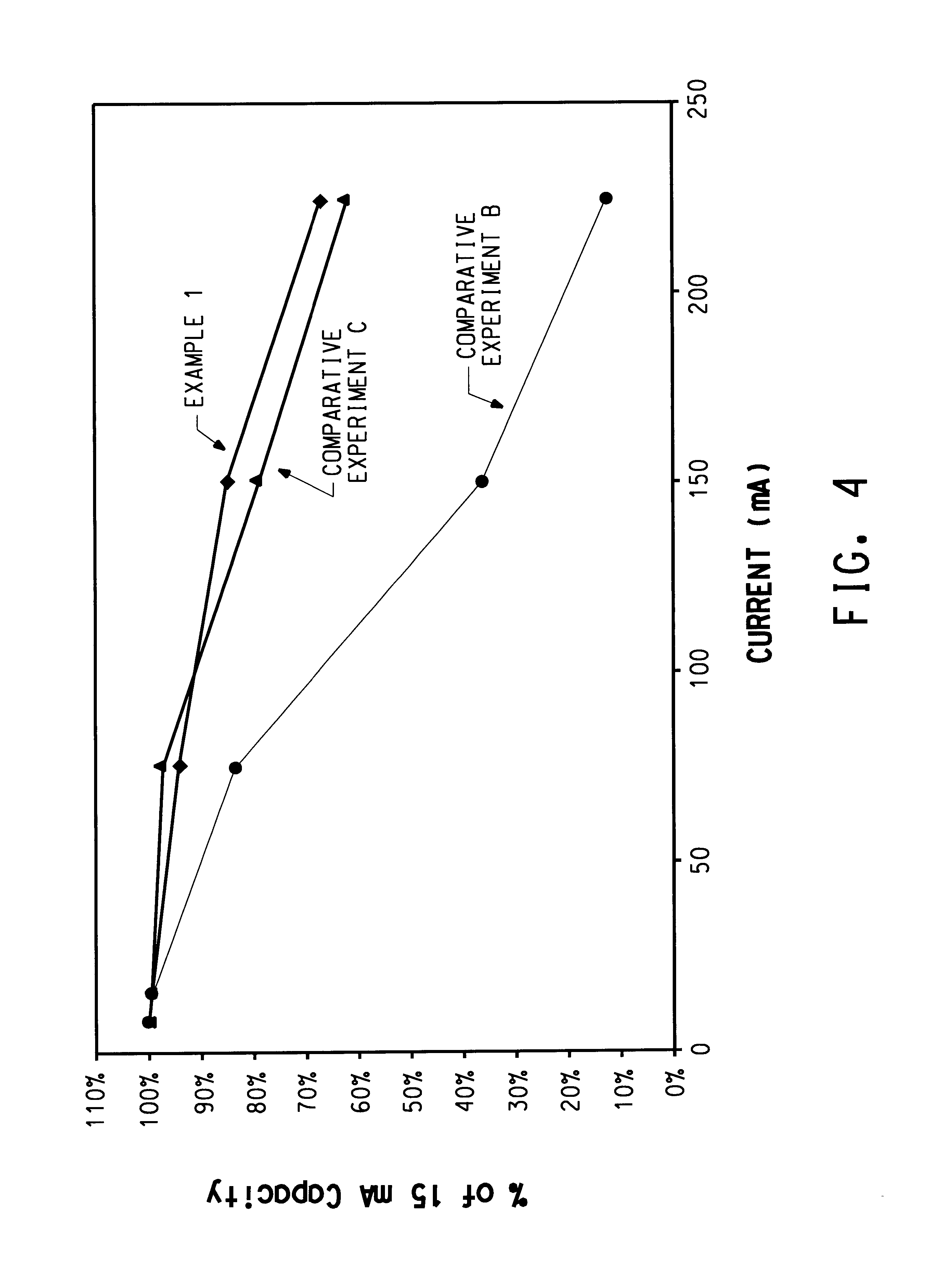
However, as shown herein below, CF.sub.3 SO.sub.3.sup.- Li.sup.+ causes a catastrophic loss of capacity retention at high discharge rates compared to the LiPF.sub.6 systems, thus eliminating batteries based upon CF.sub.3 SO.sub.3.sup.- Li.sup.+ from any application requiring any but relatively low discharge rates.
Binders, additives and impurities are also undesirable because of their potentially deleterious effects on battery performance.

Method used

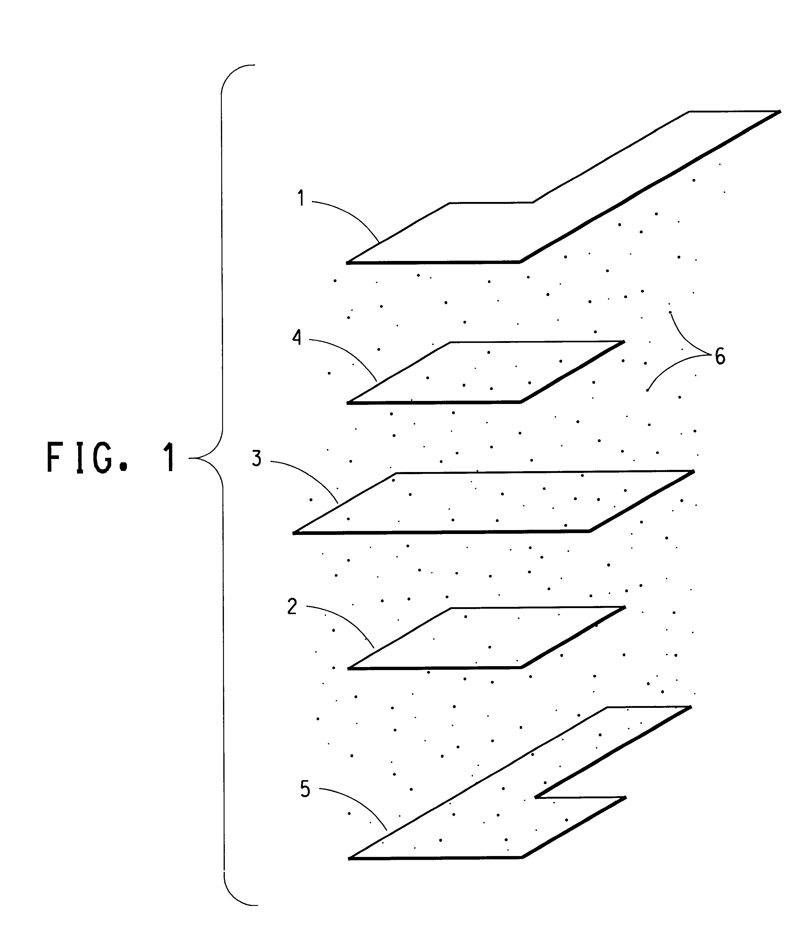
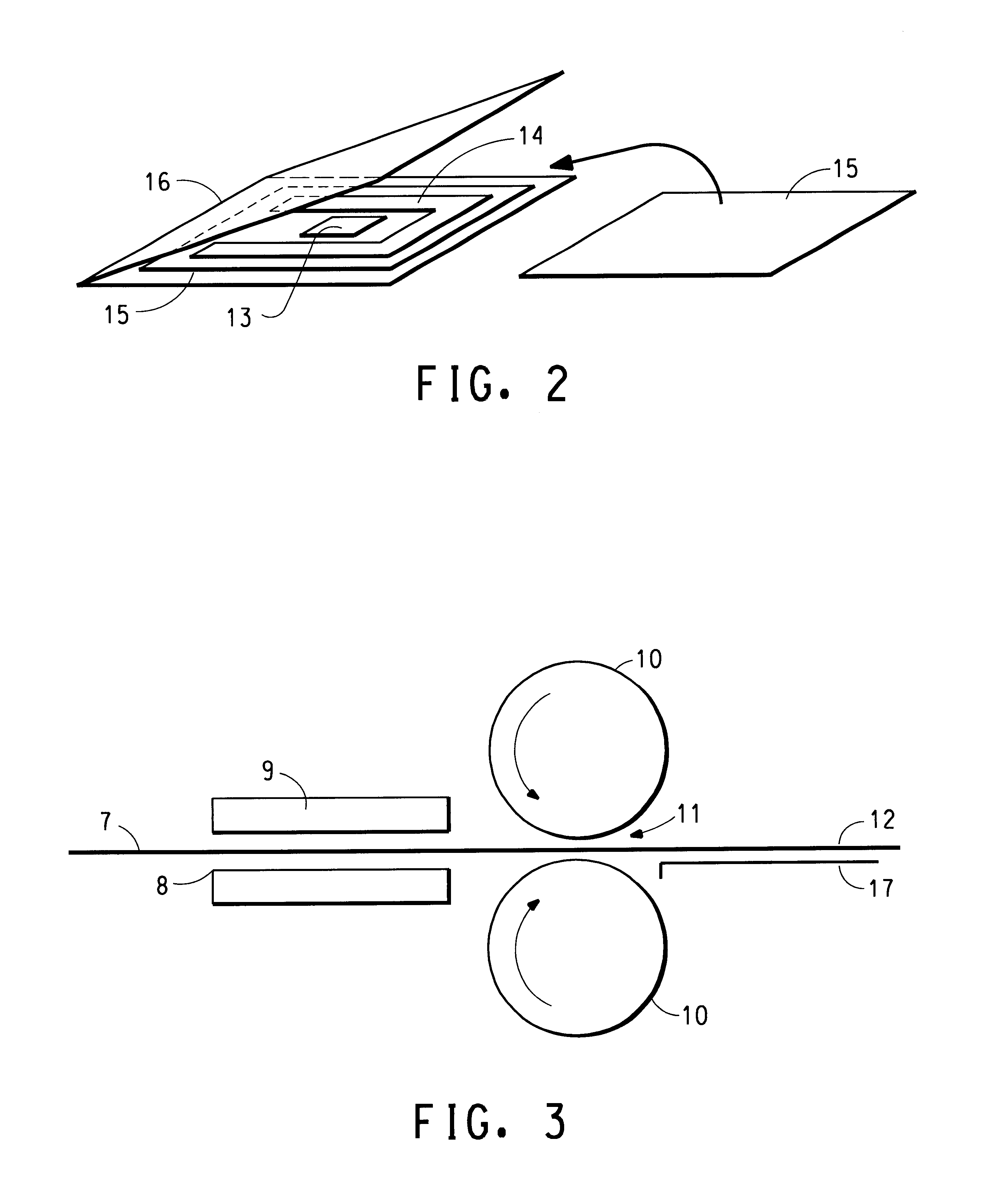

Image

  • High performance lithium or lithium ion cell
  • High performance lithium or lithium ion cell
  • High performance lithium or lithium ion cell

Examples


example 1

A cell was fabricated by the process of Gozdz et al. in U.S. Pat. Nos. 5,456,000 and 5,540,741, however flexible graphite foil was employed as the cathode current collector and the salt was (CF.sub.3 SO.sub.2).sub.2 NLi.

Cathode film was made by mixing in acetone solvent 65 parts LiCoO.sub.2 (FMC Corp.), 6.5 parts Super P carbon black (MMM Carbon), 10 parts KYNAR FLEX.RTM. 2801 (Elf Atochem), and 18.5 parts dibutyl phthalate. Films were cast using the doctor blade technique and the acetone evaporated, providing cathode with a coating weight of 19.1 mg / cm.sup.2 and a thickness as-cast of approximately 79 .mu.m. Anode film was made by mixing in acetone solvent 65 parts MCMB 2528 (Osaka Gas), 3.3 parts Super P carbon black, 10 parts KYNAR FLEX.RTM. 2801, and 21.7 parts dibutyl phthalate. After casting and acetone evaporation, the anode film had a coating weight of 17.5 mg / cm.sup.2 and a thickness of approximately 109 .mu.m. Separator film was made by mixing in acetone solvent 26 parts f...

example 2

In this embodiment, the Grafoil.RTM. of Example 1 was employed as therein described. All the solid components were dried under vacuum at 120.degree. C. and contained less than 30 ppm H.sub.2 O. Unless stated otherwise, all the processing after the drying step was carried out inside an argon-filled dry box. The binder in the electrodes and the polymer in the separator were lithium sulfonate form of a hydrolyzed copolymer of vinylidene fluoride (VF) and perfluorosulfonyl fluoride ethoxy propyl vinyl ether (PSEPVE), prepared according to the method of Doyle et al., U.S. Pat. No. 6,025,092. The polymer contained 9.about.10 mol % of PSEPVE and had a molecular weight estimated to be ca. 200,000 Da. The solvent was a 2:1 by weight mixture of ethylene carbonate (EC, battery grade from EM Industries, Hawthorne, N.Y.) and butylene carbonate (JEFFSOL.RTM. BC, Huntsman Corporation, Salt Lake City, Utah)

A cathode composition was prepared by combining, 8.7 g of the binder, 7 g of Super P carbon b...

example 3

The contact impedance of the cathode-graphite collector interface was measured as follows. Using the cathode film from Example 1, untreated Grafoil, and laminating films together at 135.degree. C., the structure C / G / C / C / G / C was fabricated, where C is cathode and G is Grafoil. Tabs of the Grafoil extended out beyond the cathodes, and the size of the cathodes was 2.2 cm.times.5.0 cm. Using a four-point-probe AC voltmeter, the impedance was measured between the two Grafoil pieces. The impedance at frequencies between 1 Hz and 10 kHz was found to be almost entirely real (resistive) with very little imaginary (capacitive) component, and of 0.5 ohm magnitude. The observed resistance was much higher than that calculated based on the bulk electrical conductivity of the cathode, hence the impedance is a measure of resistance at the interfaces between the cathodes and the current collectors. As the structure has 2 C / G interfaces in series, the contact impedance for one C / G interface was calcu...


PUM

PropertyMeasurementUnit
electrical conductivityaaaaaaaaaa
thicknessaaaaaaaaaa
charging voltageaaaaaaaaaa

Abstract

Graphite sheeting having a thickness of less than 250 micrometers and in-plane conductivity of at least 100 S / cm when employed as a cathode current collector in a lithium or lithium ion cell containing a fluorinated lithium imide or methide electrolyte salt imparts high thermal resistance, excellent electrochemical stability, and surprisingly high capacity retention at high rates of discharge.

Description

The present invention deals with lithium and lithium-ion batteries which exhibit surprisingly high capacity retention at high discharge rates and long cycle life, and with an elevated temperature melt process for the fabrication thereof.TECHNICAL BACKGROUND OF THE INVENTIONIt is known in the art to employ graphite current collectors in electrochemical cells, particularly in environments which present a risk of corrosion for metal collectors. The metal collectors, except for this potential corrosion, are preferred for their high current-carrying capability. In some cases noble metals are employed but their high costs preclude their use in most commercial applications. Most typically aluminum and copper are the materials of choice for current collectors in lithium and lithium-ion cells.Toyuguchi et al., JP-A Sho 58(1983)-115777, discloses an artificial graphite plate current collector employed in a lithium metal / polyacetylene cell wherein a solution of LiClO.sub.4 in propylene carbona...

Claims


Application Information

Patent Timeline
Patent Type & Authority Patents(United States)
IPC IPC(8): H01M10/40H01M10/36H01M4/66H01M10/04H01M6/16H01M4/02H01M10/0525H01M10/0568
CPCH01M4/663H01M4/667H01M10/0568H01M6/166H01M10/04Y10T29/49108H01M2004/021H01M2004/028H01M2300/0037H01M10/0525H01M10/058Y02E60/10Y02P70/50
Inventor DAI, HONGLI
Owner A123 SYSTEMS LLC
Learn More