Method for making micromechanical structures having at least one lateral, small gap therebetween and micromechanical device produced thereby

a micromechanical resonator and lateral technology, applied in the direction of microstructural technology, microstructure devices, solid-state devices, etc., can solve the problems of consuming a sizable portion of the total sub-system area, devices pose an important bottleneck against the ultimate miniaturization and portability of wireless transceivers, and the gap between the electrodes and the structure of the comb-driven micromechanical resonator is limited by lithography capability

Inactive Publication Date: 2005-01-25
RGT UNIV OF MICHIGAN
View PDF21 Cites 9 Cited by
  • Summary
  • Abstract
  • Description
  • Claims
  • Application Information

AI Technical Summary

Benefits of technology

An object of the present invention is to provide an improved method of making micromechanical structures having at least one lateral, small gap therebetween and a micromechanical device produced thereby.

Problems solved by technology

At present, the aforementioned resonators and discrete elements are off-chip components, and must interface with integrated electronics at board level, often consuming a sizable portion of the total sub-system area.
In this respect, these devices pose an important bottleneck against the ultimate miniaturization and portability of wireless transceivers.
The gap between the electrodes and the structure of the comb-driven micromechanical resonator is limited by lithography capability.
Therefore, a submicron gap is very difficult to do.
Although the capacitive gap of vertical micromechanical resonators, which is defined by the thickness of a sacrificial layer, can be very small, clamped-clamped beam vertical micromechanical resonators suffer from lower Q due to anchor dissipation.
Also, it normally has only one port which limits its application range.
However, the electrode-to-resonator gap for capacitively-driven lateral resonators has historically been implemented via lithography and etching, and this greatly limits the degree by which the electrode-to-resonator gap spacing can be reduced.

Method used


Image

  • Method for making micromechanical structures having at least one lateral, small gap therebetween and micromechanical device produced thereby
  • Method for making micromechanical structures having at least one lateral, small gap therebetween and micromechanical device produced thereby
  • Method for making micromechanical structures having at least one lateral, small gap therebetween and micromechanical device produced thereby

Examples


Embodiment Construction

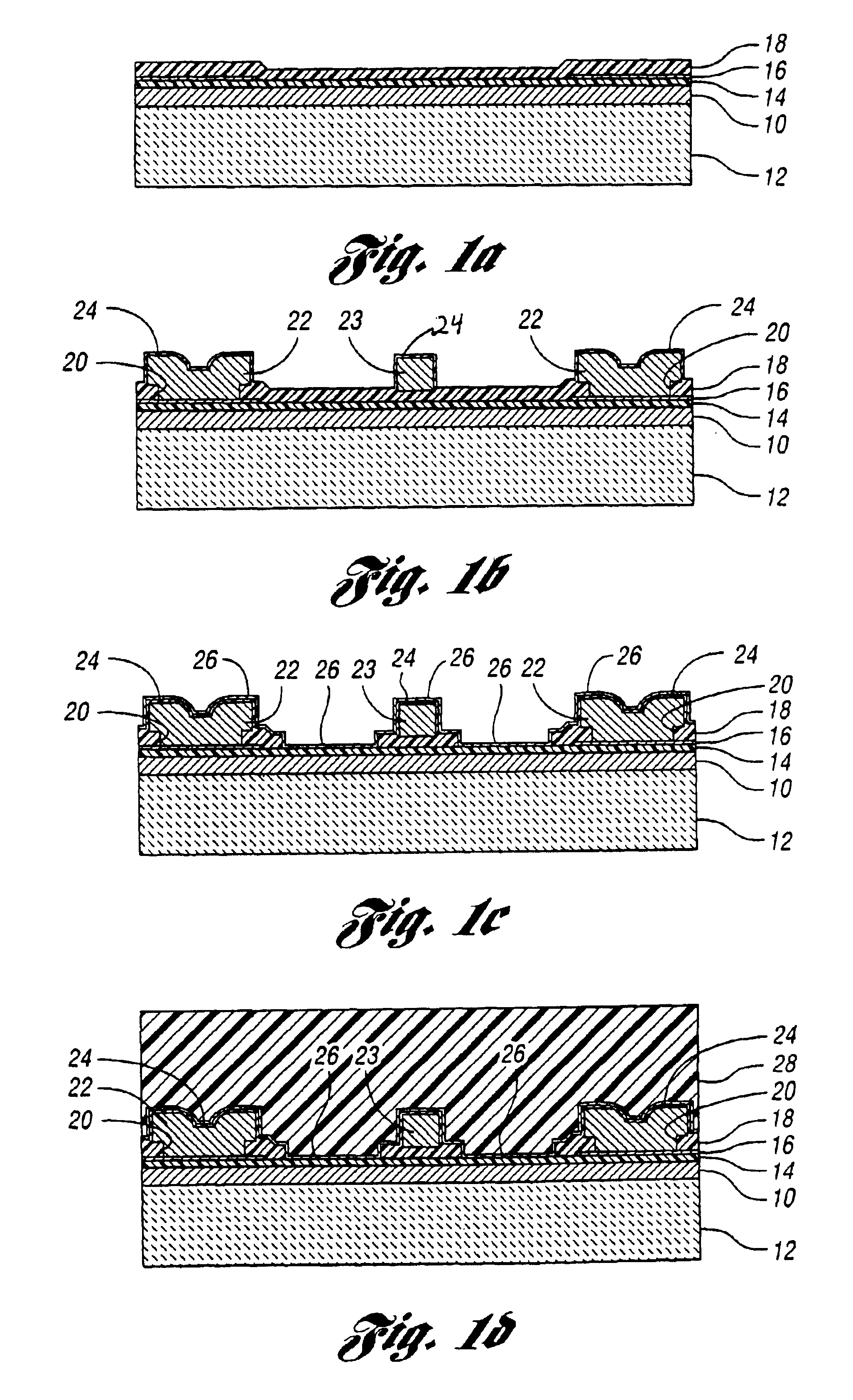
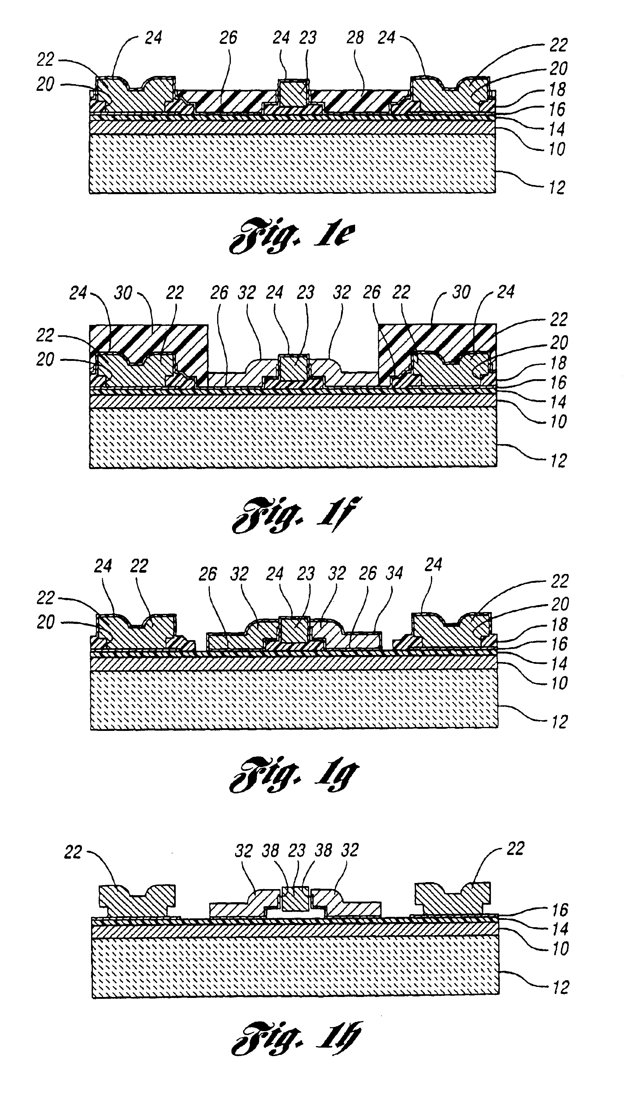
A preferred embodiment for a small-gap, lateral resonator process flow of the present invention is presented in FIGS. 1a-1h. As shown in FIG. 1a, this process starts with a 2 μm thick oxide film 10 (i.e. SiO2) thermally grown on a silicon substrate 12 and a 3000 Å thick film 14 of nitride (i.e. Si3N4) which together serve as an isolation layer. After a 3000 Å thick low stress polysilicon layer 16 is deposited via LPCVD, doped and patterned via reactive ion etching (RIE), a 5000 Å thick layer 18 of sacrificial oxide (i.e. SiO2) is deposited by LPCVD.

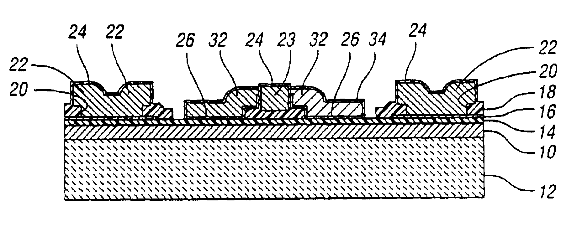
As shown in FIG. 1b, vias 20 are patterned into the sacrificial oxide layer 18 by RIE, exposing the underlying polysilicon layer 16 in specific areas to later serve as anchors for eventual structures. A 2 μm thick structural layer of low stress polysilicon is then deposited via LPCVD and patterned also via RIE to form anchor structures 22 and a resonator structure 23 with straight side walls. A 1000 Å thick layer 24 of conformal LPCVD oxi...


PUM


Abstract

A method and resulting formed device are disclosed wherein the method combines polysilicon surface-micromachining with metal electroplating technology to achieve a capacitively-driven, lateral micromechanical resonator with submicron electrode-to-resonator capacitor gaps. Briefly, surface-micromachining is used to achieve the structural material for a resonator, while conformal metal-plating is used to implement capacitive transducer electrodes. This technology makes possible a variety of new resonator configurations, including disk resonators and lateral clamped-clamped and free-free flexural resonators, all with significant frequency and Q advantages over vertical resonators. In addition, this technology introduces metal electrodes, which greatly reduces the series resistance in electrode interconnects, thus, minimizing Q-loading effects while increasing the power handling ability of micromechanical resonators.

Description

BACKGROUND OF THE INVENTION1. Field of the InventionThis invention relates to methods of making micromechanical structures having at least one lateral, small gap therebetween and micromechanical devices produced thereby.2. Background ArtVibrating mechanical tank components, such as crystal and SAW resonators, are widely used for frequency selection in communication sub-systems because of their high quality factor (Q's in tens of thousands) and exceptional stability against thermal variations and aging. In particular, the majority of heterodyning communication transceivers rely heavily on the high Q of SAW and bulk acoustic mechanical resonators to achieve adequate frequency selection in RF and IF filtering stages and to realize the required low phase noise and stability in their local oscillators. In addition, discrete inductors and variable capacitors are used to properly tune and couple the front end sense and power amplifiers, and to implement widely tunable voltage-controlled os...

Claims


Application Information

Patent Timeline
Patent Type & Authority Patents(United States)
IPC IPC(8): B81B3/00H03H9/00H03H9/50H03H9/46H03H9/24H03H9/02H03H3/00H03H3/013H03H3/007
CPCB81C1/0019B81C1/00626H03H3/007H03H3/0072H03H3/013H03H9/02362H03H9/2436H03H9/46H03H9/462H03H9/505B81B2201/0235H03H2009/02496B81B2201/0271B81B2203/0307B81C2201/0109B81B2201/0242
Inventor HSU, WAN-THAICLARK, JOHN R.NGUYEN, CLARK T. C.
Owner RGT UNIV OF MICHIGAN
Why Eureka
Try Eureka