Method of determining stray radiation lithographic projection apparatus

a technology of lithographic projection apparatus and radiation detection, which is applied in the direction of electrical apparatus, instruments, printing, etc., can solve the problems of stray radiation, small process latitude, and less resolution, and achieve the effect of increasing the sensitivity of measurement and inherent accuracy of positioning means

Active Publication Date: 2005-03-01
ASML NETHERLANDS BV
View PDF2 Cites 13 Cited by
  • Summary
  • Abstract
  • Description
  • Claims
  • Application Information

AI Technical Summary

Benefits of technology

In an embodiment of the invention the test pattern comprises a plurality of isolated areas for measuring a corresponding plurality of stray radiation parameters. An advantage is now that a more detailed analysis of the stray radiation condition of the projection system can be obtained, for example in terms of stray radiation of different ranges and/or stray radiation for different points in the field of the projection system (by providing isolated areas at different lateral positions on the mask). The more detailed analysis can be done in situ, and sufficiently fast such as to allow for intermittent checks on stray radiation during usage of the apparatus.
The plurality of features preferably comprises a one or two dimensional array or set of identical features such as, for example, opaque lines of a grating, or square, opaque areas of a checkerboard type array of isolated areas. An advantage of such an embodiment is that the sensitivity of the measurement can be increased, or that existing detectors (provided, for example, for alignment measurement or for aberra...

Problems solved by technology

In particular, the more stray radiation is present in the image of a pattern projected by the projection system, the less resolution can be obtained, and the smaller the process latitude will be.
Also, optical elements provided with anti-reflection coatings may cause stray radiation due to degradation of materials used for the anti-reflection coatings.
When the amount of stray radiation increases, the stray radiation condition deteriorates.
However, despite this situation, the spatial intensity distribution of the stray radiation in the image plane may not be symmetric with respect to the...

Method used


Image

  • Method of determining stray radiation lithographic projection apparatus
  • Method of determining stray radiation lithographic projection apparatus
  • Method of determining stray radiation lithographic projection apparatus

Examples


embodiment 1

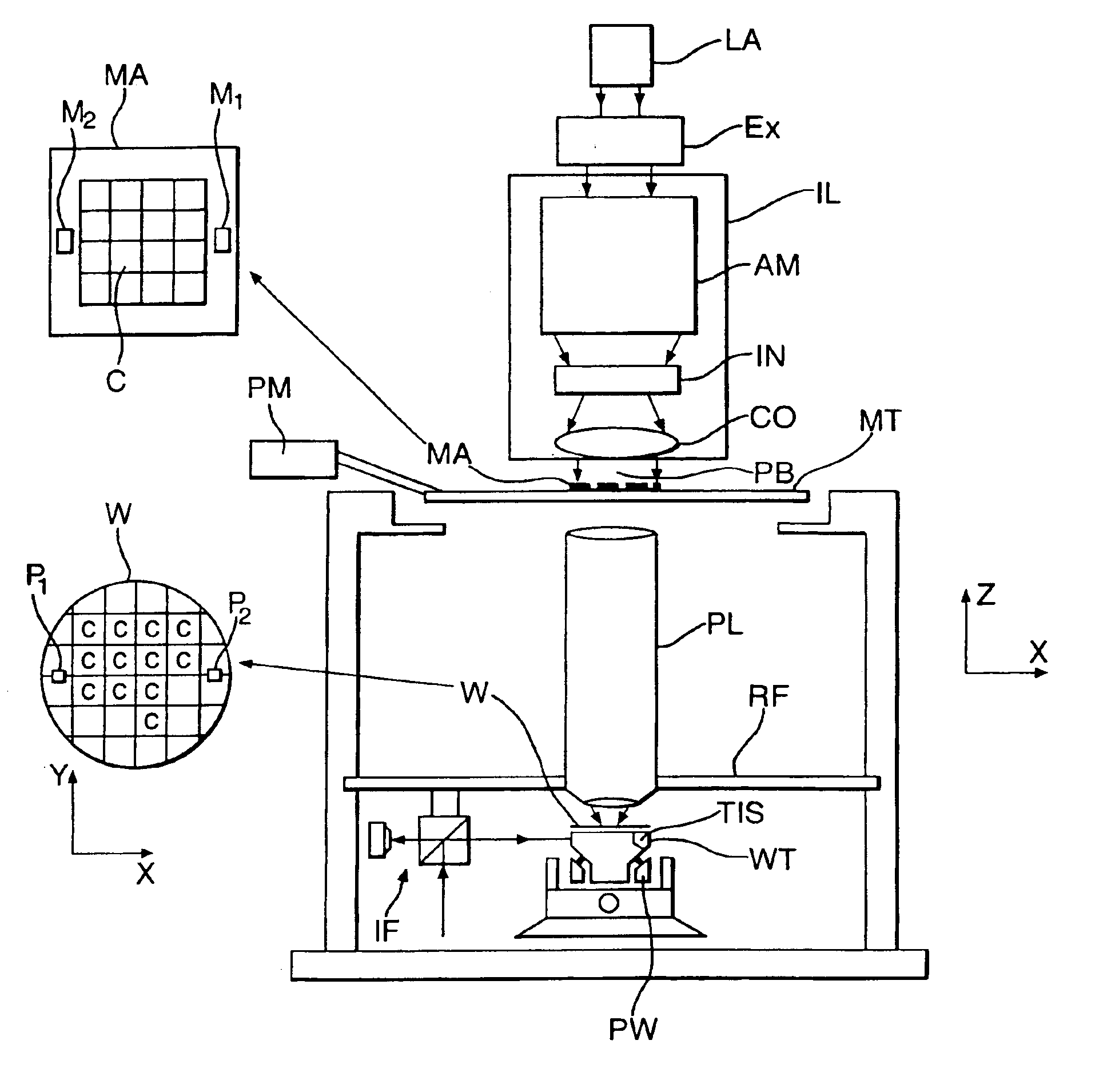
FIG. 1 schematically depicts a lithographic projection apparatus according to a particular embodiment of the invention. The apparatus comprises:a radiation system Ex, IL: for supplying a projection beam PB of radiation (e.g. UV radiation such as for example generated by an excimer laser operating at a wavelength of 248 nm, 193 nm or 157 nm, or by a laser-fired plasma source operating at 13.6 nm). In this particular case, the radiation system also comprises a radiation source LA;a first object table (mask table) MT: provided with a mask holder for holding a mask MA (e.g. a reticle), and connected to first positioning means PM for accurately positioning the mask with respect to item PL;a second object table (substrate table) WT: provided with a substrate holder for holding a substrate W (e.g. a resist-coated silicon wafer), and connected to second positioning means PW for accurately positioning the substrate with respect to item PL; anda projection system (“lens”) PL: (e.g. a quartz a...

embodiment 2

In an embodiment of the invention the test pattern comprises a series 70 of square, opaque isolated areas 10, with sides 20 of increasing length, as shown in FIG. 5. In this figure a series of three isolated areas is shown, which may for example be embodied to have a side length of respectively 160 μm, 252 μm, and 400 μm.

According to the first embodiment, stray radiation coefficients Co1, Co2 and Co3 representative, in a first approximation, for stray radiation in the ranges R1=[6 μm, infinity], R2=[17.5 μm, infinity], and R3=[36 μm, infinity] can be determined. Preferably, the test pattern comprises a plurality of series 70 at a corresponding plurality of positions in the field of the projection system, so that an assessment of the stray radiation condition of the projection system for different field positions can be made. Using the positioning means of the alignment system to subsequently position the detector aperture of the TIS at measurement positions 60 and 61, as defined wit...

embodiment 3

This embodiment is similar to the first embodiment, except as indicated below. In this embodiment, the area 10 is transmissive, and the area 11 is opaque. Also, the test pattern comprises a transmissive area of sufficient size to enable a reference measurement of the projection beam radiation intensity in the absence of effects due to opaque areas. In this area, the detected signal is S2, as described in the first embodiment. The detected radiation intensity I2 in this area is the sum of a notional intensity I21 which would be present in the absence of stray radiation, and a contribution Isr due to stray radiation in a range Rref=[0 μm, infinity]: this contribution Isr is denoted as Isr2[0 μm, infinity] and I2=I21+Isr2[0 μm, infinity].

Similarly, in position 60, the detected radiation intensity I1 (provided as a signal S1) is the sum of said notional intensity I21 and a contribution Isr1[0 μm, (½)×(SI−SD) μm] due to stray radiation in the range R1=[0, (½)×(SI−SD) μm] and

I1=I21+Isr1[0...


PUM


Abstract

A system and method for determining the stray radiation condition of a projection system, is presented herein. The invention includes providing a detector with a detector aperture coincident with the image plane of the projection system, measuring a reference parameter in accordance with the projection beam intensity, measuring a stray radiation parameter of an image of an isolated feature and calculating a coefficient representative of the stray radiation condition of the projection system based on the measured stray radiation parameter and the reference parameter. The extent of the detector aperture fits within the extent of a notional shape, which is defined by first scaling down the shape of the feature and subsequently displacing each line element constituting the edge of the scaled down shape, parallel to itself, over a distance of at least λ/NA in a direction perpendicular to that line element.

Description

BACKGROUND OF THE INVENTION1. Field of the InventionThe present invention relates to lithographic projection apparatus and more particularly to the determination of stray radiation condition therein.2. Description of the Related ArtThe term “patterning device” as here employed should be broadly interpreted as referring to means that can be used to endow an incoming radiation beam with a patterned cross-section, corresponding to a pattern that is to be created in a target portion of the substrate; the term “light valve” can also be used in this context. Generally, the said pattern will correspond to a particular functional layer in a device being created in the target portion, such as an integrated circuit or other device (see below). Examples of such a patterning device include:mask: the concept of a mask is well known in lithography, and it includes mask types such as binary, alternating phase-shift, and attenuated phase-shift, as well as various hybrid mask types. Placement of suc...

Claims


Application Information

Patent Timeline
IPC IPC(8): G03F7/20G02B13/18H01L21/027G02B13/00
CPCG03F7/70941H01L21/027
Inventor MULDER, HEINE MELLEMOERS, MARCO HUGO PETRUS
Owner ASML NETHERLANDS BV
Why Eureka
Try Eureka