
Integrated passive devices fabricated utilizing multi-layer, organic laminates

a technology of organic laminates and integrated passive devices, which is applied in the direction of waveguides, parametric amplifiers, waveguide type devices, etc., can solve the problems of high mold cost, rf filter design in most architectures, and low integration rate, and achieve the effect of higher integration

Inactive Publication Date: 2005-05-31
GEORGIA TECH RES CORP
View PDF85 Cites 81 Cited by
  • Summary
  • Abstract
  • Description
  • Claims
  • Application Information

AI Technical Summary

Benefits of technology

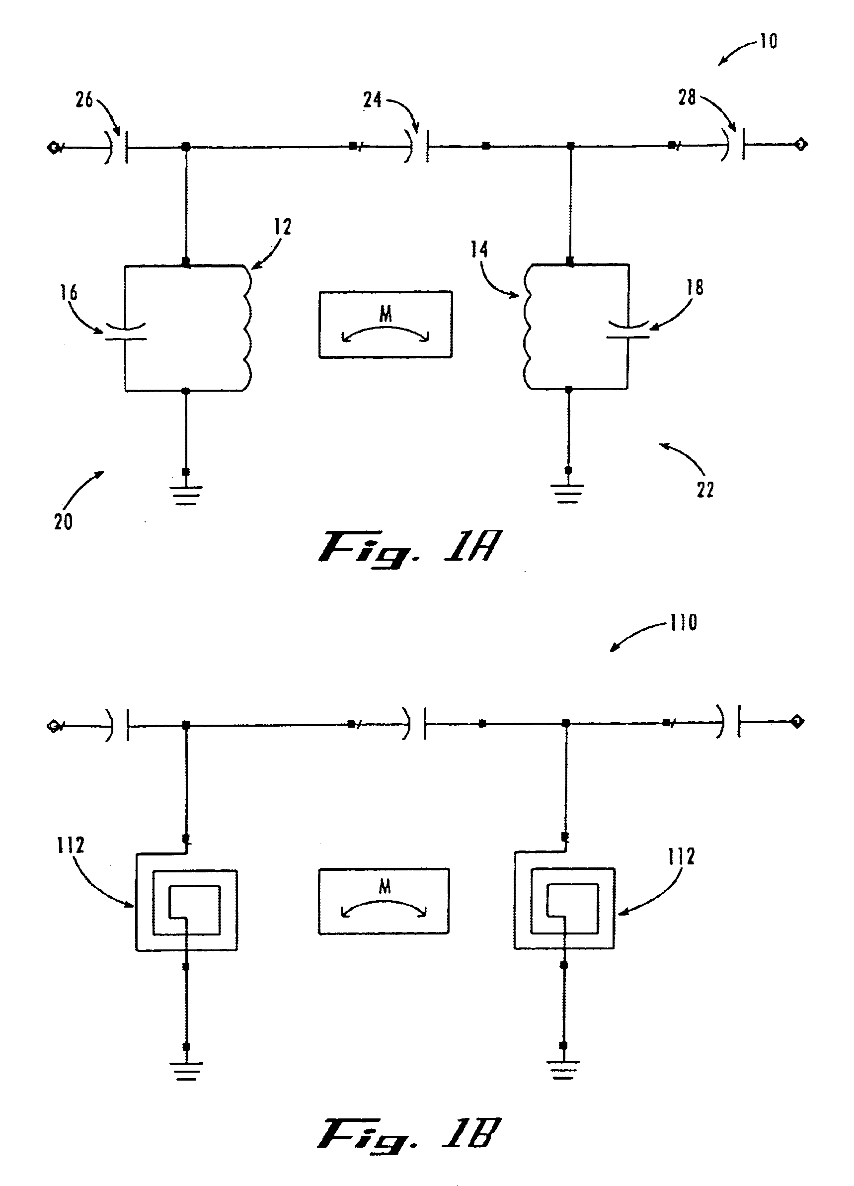
[0016]The present invention further comprises co-planar waveguide (CPW)-type topologies, which make it easy to add grounded / shunted elements. The use of CPW topologies provides for additional paths for excess currents to sink from areas of current concentration, thereby reducing coupling of devices magnetically and electrically. Additionally, CPW topologies allow for a reference voltage in proximity to the signal carrying elements, which enables components like diplexers and duplexers that need many more inductors and capacitors than what is required in a bandpass filter, low pass filter and high pass filter.
[0019]In accordance with the present invention, multi-layer filters using any suitable low cost, high performance organic (e.g., LCP and PPE) with the topology and layouts described herein can achieve the performance of not only the multilayer ceramic filters with the same form factors, but they also emulate the performance of cavity filter components in about one-tenth the volume and monoblock filters in about half the volume. Although such filter designs can be achieved in two layers, the process and design of the present invention allows for multiple layer (>2 layer) capacitors and inductors integrated to form even more compact devices having higher integration.
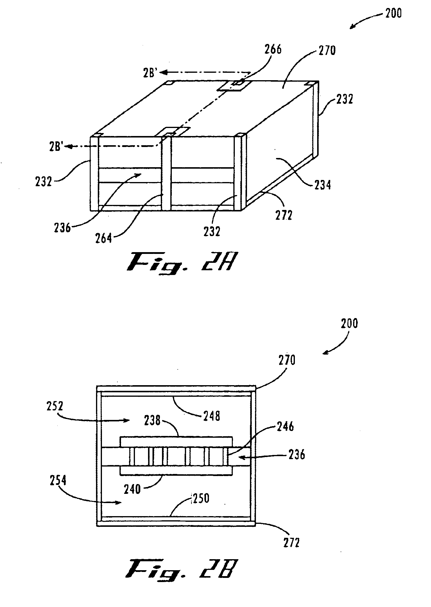
[0020]For example, a two pole filter constructed in accordance with the present invention using two metal layers on two sides of a thin laminate substrate and then shielded on both sides has a footprint of 3×3 mm, a height of 1.5 mm and emulates the performance of a 4×5 mm monoblock filter having a height of 1.8 mm. On a 12″×12″ substrate, it is possible to fabricate approximately 6500 such components with filter-to-filter spacing included, which illustrates its cost effectiveness. A filter according to the present invention requires just two patterned metal layers because of the CPW-type topology, as compared to the multi-layers in ceramic filters or molded cavity filters. This also reduces design time, processing time, and fabrication cost as compared to ceramic filters or molded cavity filters.

Problems solved by technology

The design of RF filters in most architectures is becoming a problem since center frequencies are scaling towards the multi-gigahertz range for most RF standards.
However, there are several disadvantages to ceramic coaxial cavity or monoblock filters.
For example, mold for these filters is expensive and each new design usually needs a new mold.
Yet further, such filters are typically fastened to some mounting support in a mechanically reliable manner, which adds to the difficulty and cost of the manufacturing process.
Due to other fundamental limits on the technology, the MLC and LTCC filters do not perform as well as the cavity filters.
For example, one limitation is in the lack of flexibility of choosing a thickness (e.g., 4 mil<thickness<8 mil) of the dielectric sheets that make up the ceramic components.
Additionally, the multilayer ceramic filters come with the disadvantage of higher costs due to the non-traditional processes used in making the multilayer ceramic filters.
While realizing the problems with ceramic and advantages with organic laminate processing in terms of costs, filters fabricated in organic substrastes generally have not delivered the performance of cavity filters or multilayer ceramic filters.
The bandwidths realized by the organic filters have not been small enough and the insertion loss too high for even large bandwidth applications.
Thus, there is an unsatisfied need in the industry for a high frequency, low loss, inexpensive bandpass filter having a relatively small footprint.

Method used


Image

  • Integrated passive devices fabricated utilizing multi-layer, organic laminates
  • Integrated passive devices fabricated utilizing multi-layer, organic laminates
  • Integrated passive devices fabricated utilizing multi-layer, organic laminates

Examples


example i

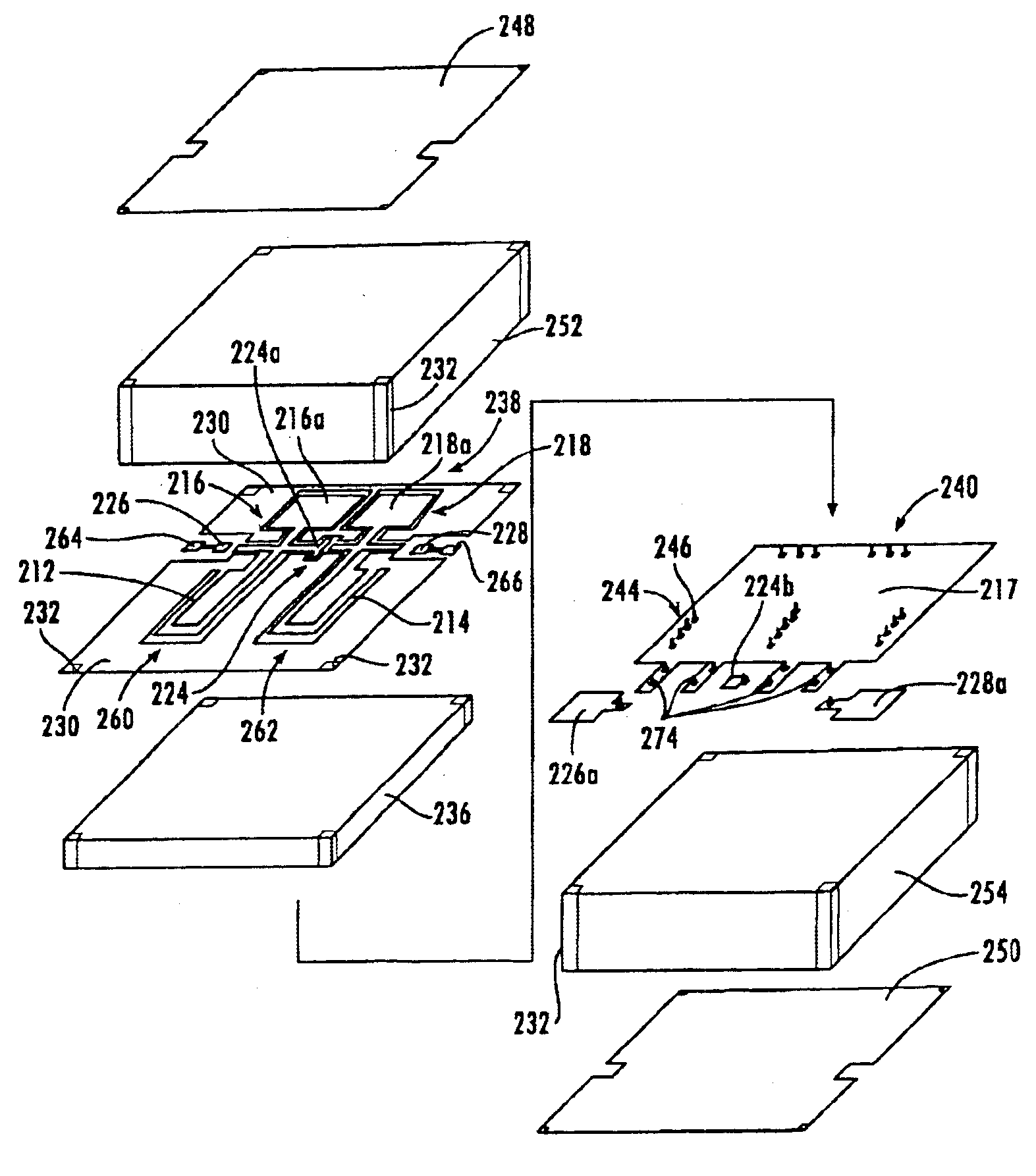
[0074]An X-ray photograph of an organic bandpass filter 500 in accordance with an embodiment of the present invention is provided in FIGS. 7 and 8. The filter 500 comprises shorted hybrid CPW-stripline meander transmission line inductors 512, 514 formed close to each other on a first organic dielectric layer, which is a 50 μm thick layer of LCP, wherein the inductors 512, 514 are directly magnetically coupled to each other. Each inductor is connected to separate parallel plate capacitors 516, 518 by sandwiching the same dielectric sheet. An inter-resonator parallel plate coupling capacitor 524, is formed using two disconnected metal plates that sandwich the same organic dielectric sheet in such a manner that the each plate of the inter-resonator coupling capacitor electrode connects to separate inductors. In addition, a second organic dielectric layer and a third organic dielectric layer sandwich the first organic dielectric layer, and comprise a high frequency hydrocarbon material ...

example ii

[0085]Another organic bandpass filter 600 in accordance with an embodiment of the present invention is shown in the picture of FIG. 10. The filter 600 comprises shorted hybrid CPW-microstrip, meander inductors 612, 614 formed close to each other on a first organic dielectric layer, which is a layer of LCP, directly magnetically coupled to each other. The term “shorted” refers to one end of each inductor connected to the large metallic area, which in this case serves as the in-built shield 630 (also referred to as a coplanar ground ring). In addition, the filter 600 includes an inter-resonator parallel plate coupling capacitor electrode 624 with in-built shield 630 formed using two disconnected metal plates that sandwich the first organic dielectric layer in such a manner that the each plate of the inter-resonator coupling capacitor electrode connects to separate resonators. Yet further, the filter 600 includes a first shield electrode formed respectively on a second organic dielectr...

example iii

[0094]Yet another organic bandpass filter 700 in accordance with an embodiment of the present invention is shown in the picture of FIG. 12. The organic bandpass filter 700 comprises shorted hybrid CPW-microstrip meander inductors formed close to each other on a first organic dielectric substrate, such as epoxy based Vialux by E. I. du Pont de Nemours and Company, directly magnetically coupled to each other. In addition, the third bandpass filter comprises an inter-resonator parallel plate coupling capacitor electrode 724, with ground ring, formed using two disconnected metal plates that sandwich the same organic dielectric sheet in such a manner that the each plate of the inter-resonator coupling capacitor electrode connects to separate resonators.

[0095]The transmission line inductors 712, 714 did not provide the needed capacitance in the desired length. Since the dielectric is lossy for the capacitor application, each is replaced by a separate discrete capacitor 702, such as a chip...


PUM


Abstract

The present invention includes an organic device that can be integrated in a multilayer board made of organic material. The passive devices can be integrally fabricated on a circuit board in either surface mount device (SMD) or ball grid array (BGA) form. Alternatively, the passive device can be constructed in a stand alone SMD or BGA / chip scale package (CSP) form to make it mountable on a multilayer board, ceramic carrier or silicon platform in the form of an integrated passive device. The passive device includes side shielding on two sides in the SMD form and four sides in the BGA / CSP form. The side shielding can be external or in-built.

Description

CROSS-REFERENCE TO RELATED APPLICATIONS[0001]This application is related to the following co-pending, commonly assigned U.S. applications, each of which is entirely incorporated herein by reference: “Methods for Fabricating Three-Dimensional All Organic Interconnect Structures” filed Mar. 28, 2003, and accorded application Ser. No. 10 / 402,315; and “Stand-Alone Organic-Base Passive Devices” filed Mar. 28, 2003, and accorded application Ser. No. 10 / 405,024.STATEMENT OF GOVERNMENT INTEREST[0002]The work that led to this invention has been supported in part by a grant from the U.S. Army, Contract No. DAAH01-99-D-R002-0032. Thus, the United States Government may have certain rights to this invention.BACKGROUND OF THE INVENTION[0003]I. Field of the Invention[0004]The present invention generally relates to the fabrication of integrated passive devices, and more particularly, to topologies for passive filters fabricated utilizing organic laminates.[0005]II. Description of Related Art[0006]R...

Claims


Application Information

Patent Timeline
IPC IPC(8): H01L21/48H01F41/04H01L25/065H01L21/02H01L27/08H01P1/203H01P1/20H03H7/38H01F17/00
CPCH01F41/041H01L21/4857H01L25/0652H01L27/08H01P1/20381H03H7/38H01F17/0033H01L2924/09701H01L2924/0002H01L2924/3011H01L2924/00H01P1/203H03H7/01H01P1/205
Inventor WHITE, GEORGE E.SWAMINATHAN, MADHAVANSUNDARAM, VENKATESHDALMIA, SIDHARTH
Owner GEORGIA TECH RES CORP
Learn More