Semiconductor structures using a group III-nitride material system with reduced phase separation and method of fabrication
a technology of nitride and material, applied in the field of semiconductor structure and process, can solve the problems of increased threshold current, reduced light emission efficiency, large operating current, etc., and achieve the effects of reducing phase separation, reducing defect densities, and improving emission efficiency
- Summary
- Abstract
- Description
- Claims
- Application Information
AI Technical Summary
Benefits of technology
Problems solved by technology
Method used
Image
Examples
first embodiment
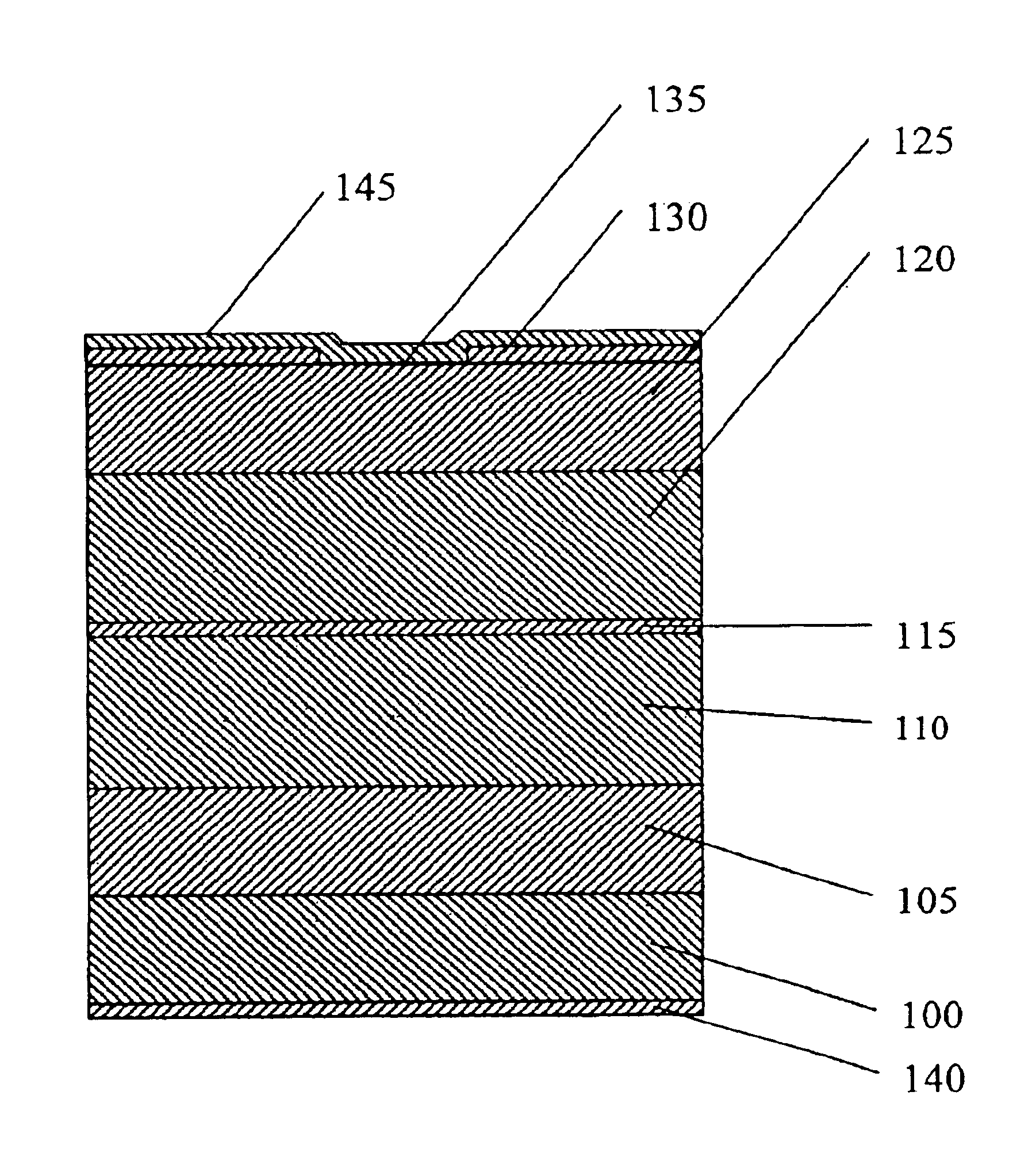
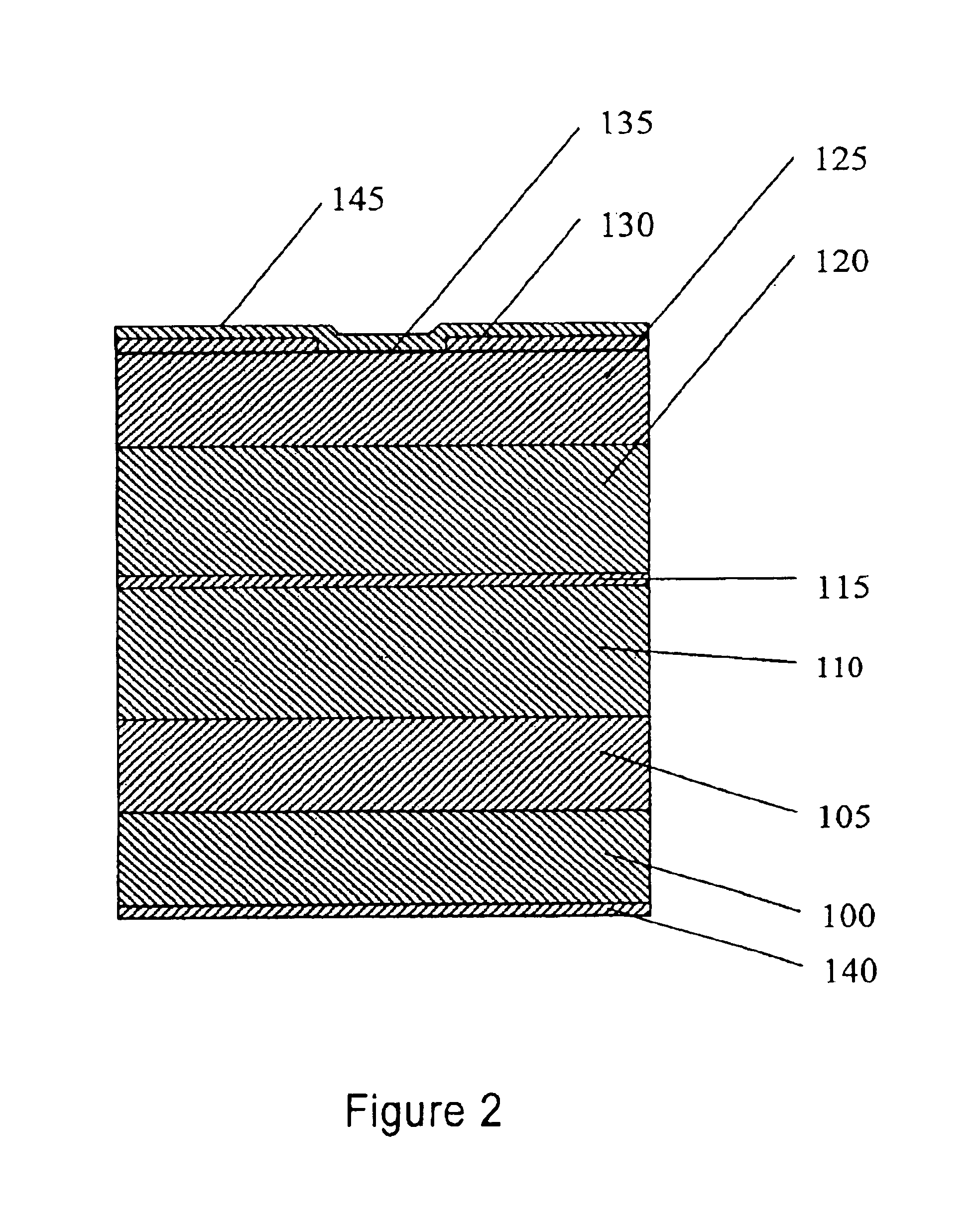
[0081]Referring first to FIG. 2, shown therein in cross-sectional view is a semiconductor structure according to the invention. For purposes of illustration, the semiconductor structure shown in many of the Figures will be a laser diode, although the present invention has application to a number of device types. With particular reference to FIG. 1, an n-type GaN substrate 100 is provided and an n-type GaN first cladding layer 105 (typically 0.5 μm thick) is formed thereon. Thereafter, a second cladding layer 110, typically of an n-type In0.05Ga0.75Al0.2N material which may be on the order of 1.5 μm thick, is formed thereon, followed by a multiple quantum well active layer 115 which is an exemplary arrangement may comprise three quantum well layers of In0.01Ga0.96Al0.03N material on the order of 35 A thick together with four barrier layers on In0.02Ga0.85Al0.13N material on the order of 35 A thick, arranged as three pairs. Next, a third cladding layer 120 of a p-type In0.05Ga0.75Al0....
second embodiment
[0093]FIG. 6 shows in graph form the emitted light versus drive current characteristics of a laser diode in accordance with the The laser diode is driven with a cw current. The threshold current is found to be 32.5 mA.
[0094]Referring next to FIGS. 7A-7E, a summary of the key fabrication steps is shown for an exemplary device of a semiconductor laser diode in accordance with the second embodiment.
[0095]Referring first to FIGS. 7A and 7B, the formation of the first and second cladding layers 105 and 110 on an n-type GaN substrate 100, together with the three-pair multiple quantum well active layer 115 are the same as for the first embodiment. Thereafter, the third and fourth cladding layers 120 and 125 are formed and then partially removed—typically by etching—to create a ridge structure 500. As before, in an exemplary embodiment the various layers are formed successively by either the MOCVD or the MBE method.
[0096]Then, as shown in FIGS. 7C-7E, a silicon dioxide layer 130 is formed ...
third embodiment
[0100]FIG. 9 shows a plot of the emitted light versus drive current characteristics of the laser diode in accordance with the The laser diode is driven with a pulsed current with a duty cycle of 1%. The threshold current density is found to be 5.0 kA / cm2.
[0101]FIGS. 10A-10D show a series of the fabrication steps of a semiconductor laser diode in one example of the third embodiment. It will be appreciated that the fabrication steps are the same as those described in connection with FIGS. 4A-4D, and therefore are not further described.
[0102]Referring next to FIG. 11, a fourth embodiment of the present invention may be better appreciated. The fourth embodiment, like the third embodiment, is designed to emit blue light and therefore has the same mole fractions as the third embodiment. However, like the second embodiment, the fourth embodiment is configured to provide a ridge structure to serve as a waveguide. Because the mole fractions are similar to those of FIG. 8, similar elements w...
PUM
 Abstract
Description
Claims
Application Information
 - R&D
- Intellectual Property
- Life Sciences
- Materials
- Tech Scout
- Unparalleled Data Quality
- Higher Quality Content
- 60% Fewer Hallucinations
Browse by: Latest US Patents, China's latest patents, Technical Efficacy Thesaurus, Application Domain, Technology Topic, Popular Technical Reports.
© 2025 PatSnap. All rights reserved.Legal|Privacy policy|Modern Slavery Act Transparency Statement|Sitemap|About US| Contact US: help@patsnap.com


