
Copper technology for ULSI metallization

a technology of copper and ulsi, applied in the field of damascene structure formation in semiconductor devices, can solve the problems of poor adhesion of copper to interlayer dielectrics, particularly siosub>2/sub>, and the disassembly of active devices, so as to reduce the diffusion of copper atoms and reduce the processing steps

Inactive Publication Date: 2005-07-19
MICRON TECH INC
View PDF15 Cites 66 Cited by
  • Summary
  • Abstract
  • Description
  • Claims
  • Application Information

AI Technical Summary

Benefits of technology

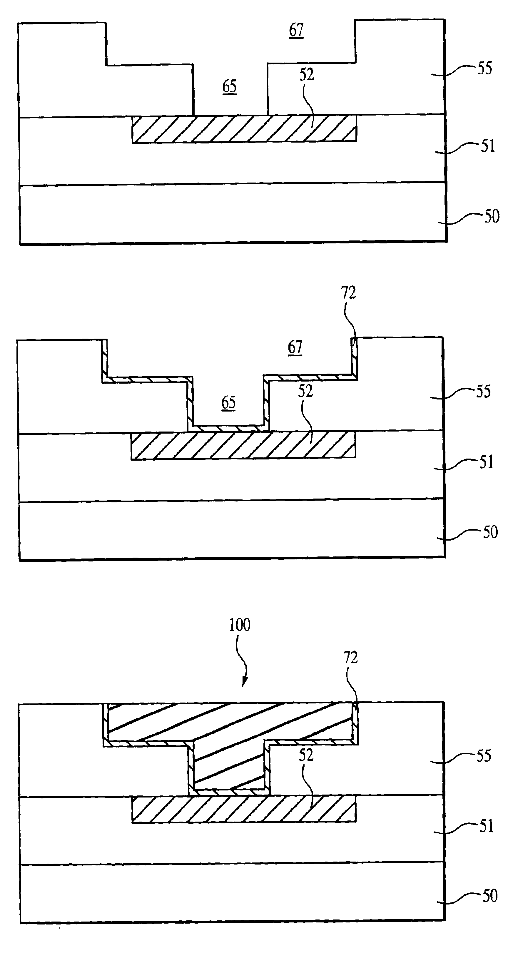
[0007]The present invention provides a method for fabricating a copper interconnect structure in a semiconductor device which requires fewer processing steps and reduces the diffusion of copper atoms to underlying damascene layers.

Problems solved by technology

Unfortunately, copper diffuses rapidly through silicon dioxide (SiO2) or other interlayer dielectrics, such as polyimides and parylenes, and copper diffusion can destroy active devices, such as transistors and capacitors, formed in the IC substrate.
In addition, metal adhesion to the underlying substrate materials must be excellent to form reliable interconnect structures but the adhesion of copper to interlayer dielectrics, particularly to SiO2, is generally poor.
Another problem associated with dual damascene processing is the cost and complexity of the process.
Thus, although copper dual damascene process is more advantageous over the copper single damascene process, one big disadvantage remains the high number of sequential photoresist / mask / etch steps and etch-stop layers which, as described above, are conventionally used in damascene processing and which increase the fabrication cost and reduce the production yield.
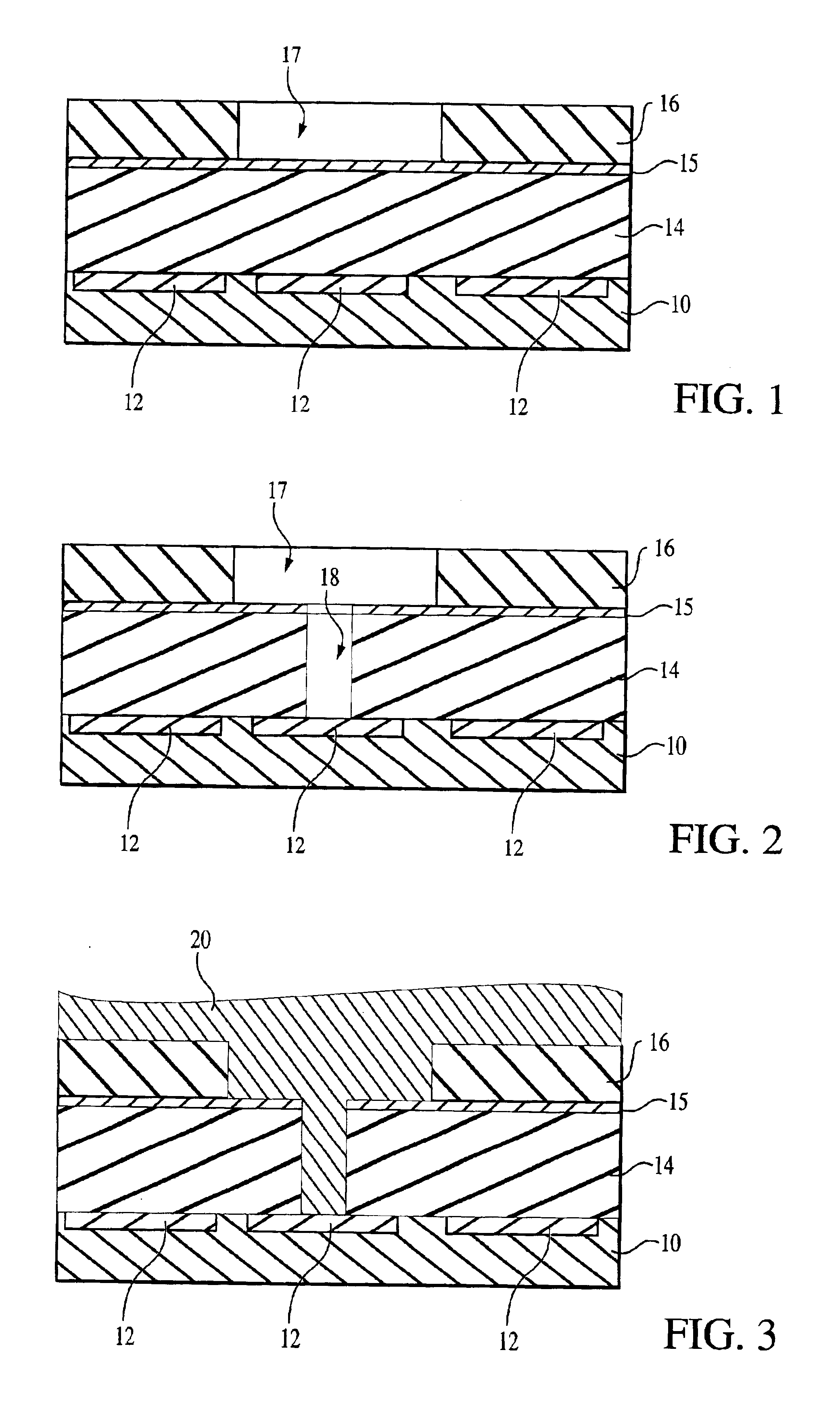
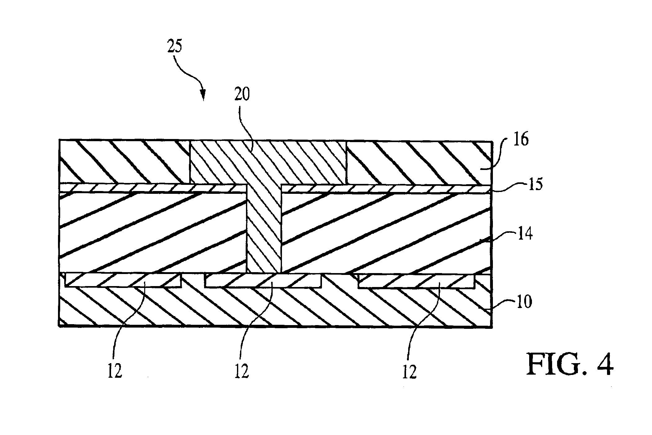
Another disadvantage is that copper deposition methods for conventional damascene processes employ a large amount of high-purity copper material, of which a considerable amount is removed and wasted by the CMP process described above with reference to FIGS. 3-4.
Thus, even the dual damascene processing is very expensive and entails a large number of processing steps.

Method used


Image

  • Copper technology for ULSI metallization
  • Copper technology for ULSI metallization
  • Copper technology for ULSI metallization

Examples


Embodiment Construction

[0028]In the following detailed description, reference is made to various specific embodiments in which the invention may be practiced. These embodiments are described with sufficient detail to enable those skilled in the art to practice the invention, and it is to be understood that other embodiments may be employed, and that structural, electrical and process changes may be made without departing from the spirit or scope of the present invention.

[0029]The term “substrate” used in the following description may include any semiconductor-based structure that has a semiconductor surface. The term should be understood to include silicon, silicon-on insulator (SOI), silicon-on sapphire (SOS), doped and undoped semiconductors, epitaxial layers of silicon supported by a base semiconductor foundation, and other semiconductor structures. The semiconductor need not be silicon-based. The semiconductor could be silicon-germanium, germanium, or gallium arsenide. When reference is made to a “sub...


PUM

PropertyMeasurementUnit
thicknessaaaaaaaaaa
thicknessaaaaaaaaaa
temperatureaaaaaaaaaa

Abstract

A copper damascene structure formed by direct patterning of a low-dielectric constant material is disclosed. The copper damascene structure includes a tungsten nitride barrier layer formed by atomic layer deposition using sequential deposition reactions. Copper is selectively deposited by a CVD process and / or by an electroless deposition technique.

Description

FIELD OF THE INVENTION[0001]The present invention relates to the field of semiconductors and, in particular, to a method of forming damascene structures in semiconductor devices.BACKGROUND OF THE INVENTION[0002]In an attempt to improve the performance, reliability and density of fully integrated ULSI (ultra-large scale integration) interconnects, the microelectronics industry has recently begun migrating away from the use of aluminum (Al) and / or its alloys for the ULSI interconnects. As such, advanced dual damascene processes have begun using copper (Cu) as the material of choice because copper has high conductivity, extremely low resistivity (about 1.7 μΩcm) and good resistance to electromigration. Unfortunately, copper diffuses rapidly through silicon dioxide (SiO2) or other interlayer dielectrics, such as polyimides and parylenes, and copper diffusion can destroy active devices, such as transistors and capacitors, formed in the IC substrate. In addition, metal adhesion to the und...

Claims


Application Information

Patent Timeline
Patent Type & Authority Patents(United States)
IPC IPC(8): H01L21/285H01L21/288H01L21/02H01L21/321H01L21/768H01L21/70
CPCH01L21/28556H01L21/28562H01L21/288H01L21/3212H01L21/76807H01L21/76843H01L21/76874
Inventor AHN, KIE Y.FORBES, LEONARD
Owner MICRON TECH INC
Learn More