
Tightly coupled software protocol decode with hardware data encryption

a hardware data encryption and software protocol technology, applied in the field of data encryption, can solve the problems of reducing the overall performance of the switch, affecting performance, and reducing performance, so as to reduce the latency of encryption setup, and efficiently cooperate with other resources of the processor

Inactive Publication Date: 2005-07-19
CISCO TECH INC
View PDF90 Cites 34 Cited by
  • Summary
  • Abstract
  • Description
  • Claims
  • Application Information

AI Technical Summary

Benefits of technology

[0013]The invention relates to an encryption mechanism that tightly-couples hardware data encryption functions with software-based protocol decode processing within a pipelined processor of a programmable processing engine. Tight-coupling is achieved by a micro-architecture of the pipelined processor that allows encryption functions to be accessed as a novel encryption execution unit of the processor. As described herein, such coupling substantially reduces the latency associated with conventional hardware / software interfaces.
[0014]Specifically, the mechanism comprises, in part, an integrated software and hardware interface that enables the encryption execution unit to efficiently cooperate with other resources of the processor. An instruction decoder of the processor issues instructions, including native encryption opcodes, directly to the encryption execution unit to thereby substantially reduce encryption setup latency. These native encryption-opcodes are provided within the processor's instruction set and constitute the software portion of the interface that enables selective access to the encryption execution unit.
[0015]In the illustrative embodiment, the processor is embodied as customized micro-controller core having a multi-stage pipeline architecture that includes, inter alia, an execution stage of arithmetric logic units. The novel encryption execution unit is preferably a specialized encryption tightly coupled state machine (TCSM) unit that is selectively invoked within the execution stage. In response to decode processing of the native op codes, the encryption TCSM unit is invoked to perform encryption / decryption functions that utilize the hardware interface of the processor to access the processor's resources, including a plurality of high-performance internal busses that faciliate overlapping of operations. For instance, the encryption TCSM unit can simultaneously load an encryption key while storing a previous encryption result. Overlapping of operations improves encryption throughput by further reducing latency typically associated with a conventional encryption hardware module attached to a processor's external bus.
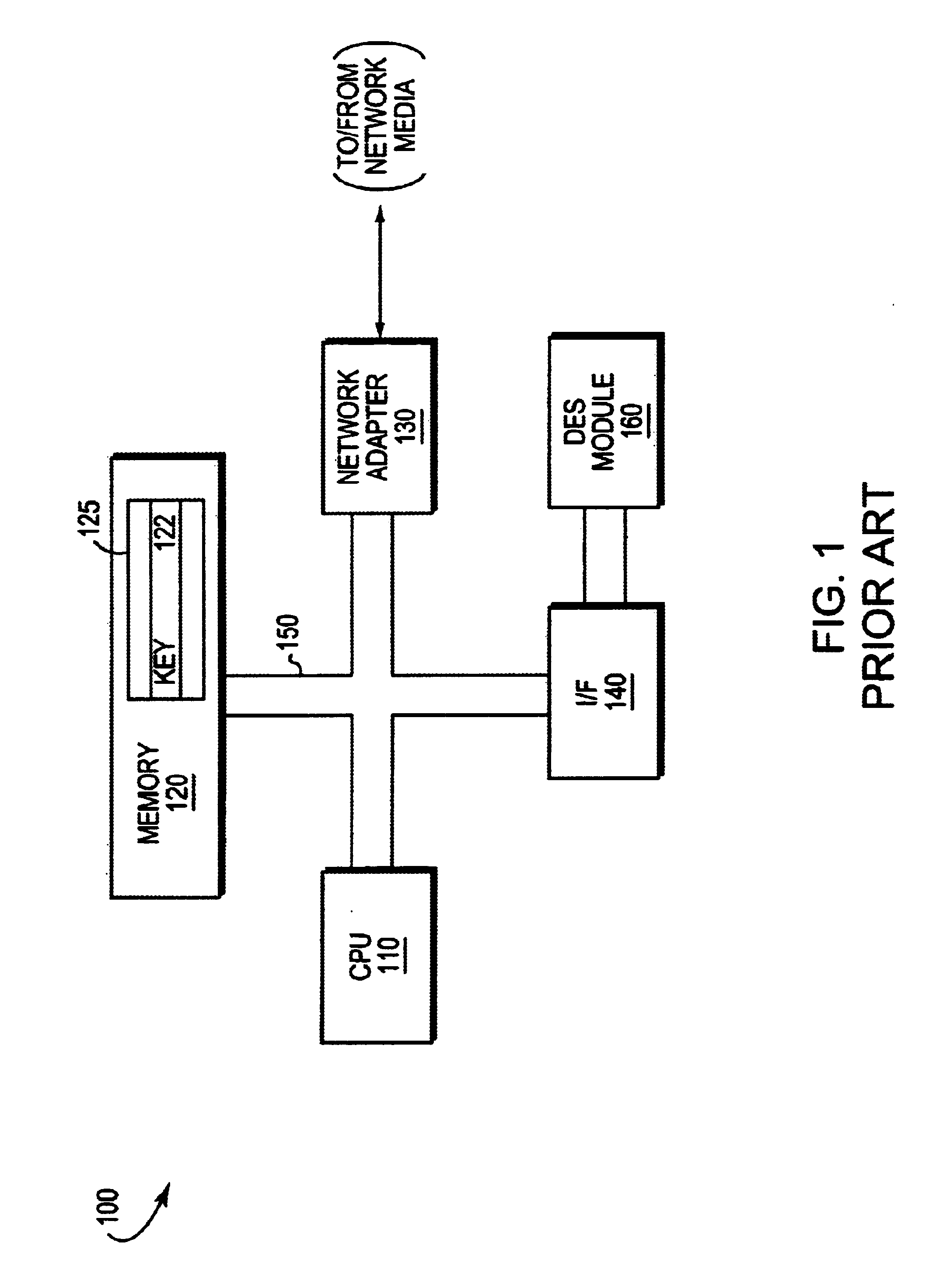
[0016]Advantageously, the inventive mechanism provides speed-up enhancements for the entire data encryption / decryption function. That is, the encryption mechanism eliminates at least two complete local bus transfers wherein each transfer comprises four 64-bit transfers along with latencies associated with traversing the external interface circuitry. Use of the specialized encryption TCSM unit obviates the physical limitation associated with pin counts of a hardware module coupled to the bus. The inventive mechanism substantially increases throughput of the memory subsystem by eliminating the shared memory bandwidth capability of the external interface between the system bus and a conventional DES module. Moreover, CPU notification of data encryption / decryption completion (interrupt-driven or polling) is eliminated by the invention, thereby reducing latencies and bandwidth associated with such notification.

Problems solved by technology

The resulting interface between software executing on the processor and the hardware encryption module substantially reduces the overall performance of the switch.
Performance is adversely affected primarily because of the memory and input / output (I / O) bandwidth consumed by the encryption module when interacting with components of the switch; in addition, the overhead required to pass encryption keys and data to and from the module, e.g., over a bus contributes to the reduction in performance.
Since different protocols define different ways of encoding packets (see RFC 1827), hardware implementation of data encryption / decryption is generally complex and inefficient.
Software protocol processing may therefore contribute to the latency associated with the encryption / decryption function.
When multiplexing packets over the bus, however, constant reloading of the keys may be required.
Because of the previous protocol decode, the cleartext / ciphertext data transfer may cause a non-aligned access which must be subsequently aligned, thereby creating additional latency as well as consuming a significant amount of the bus bandwidth.
However, an interrupt initiated by the hardware module causes the state of the processor to change while the interrupt is serviced; in this case, latency of the interrupt service routine is added to the overall latency.
It is apparent that data encryption / decryption by the hardware module arrangement described above entails substantial data movement over the system bus of the switch, thereby causing a “bottleneck” on the bus that adversely affects the performance of the switch.

Method used


Image

  • Tightly coupled software protocol decode with hardware data encryption
  • Tightly coupled software protocol decode with hardware data encryption
  • Tightly coupled software protocol decode with hardware data encryption

Examples


Embodiment Construction

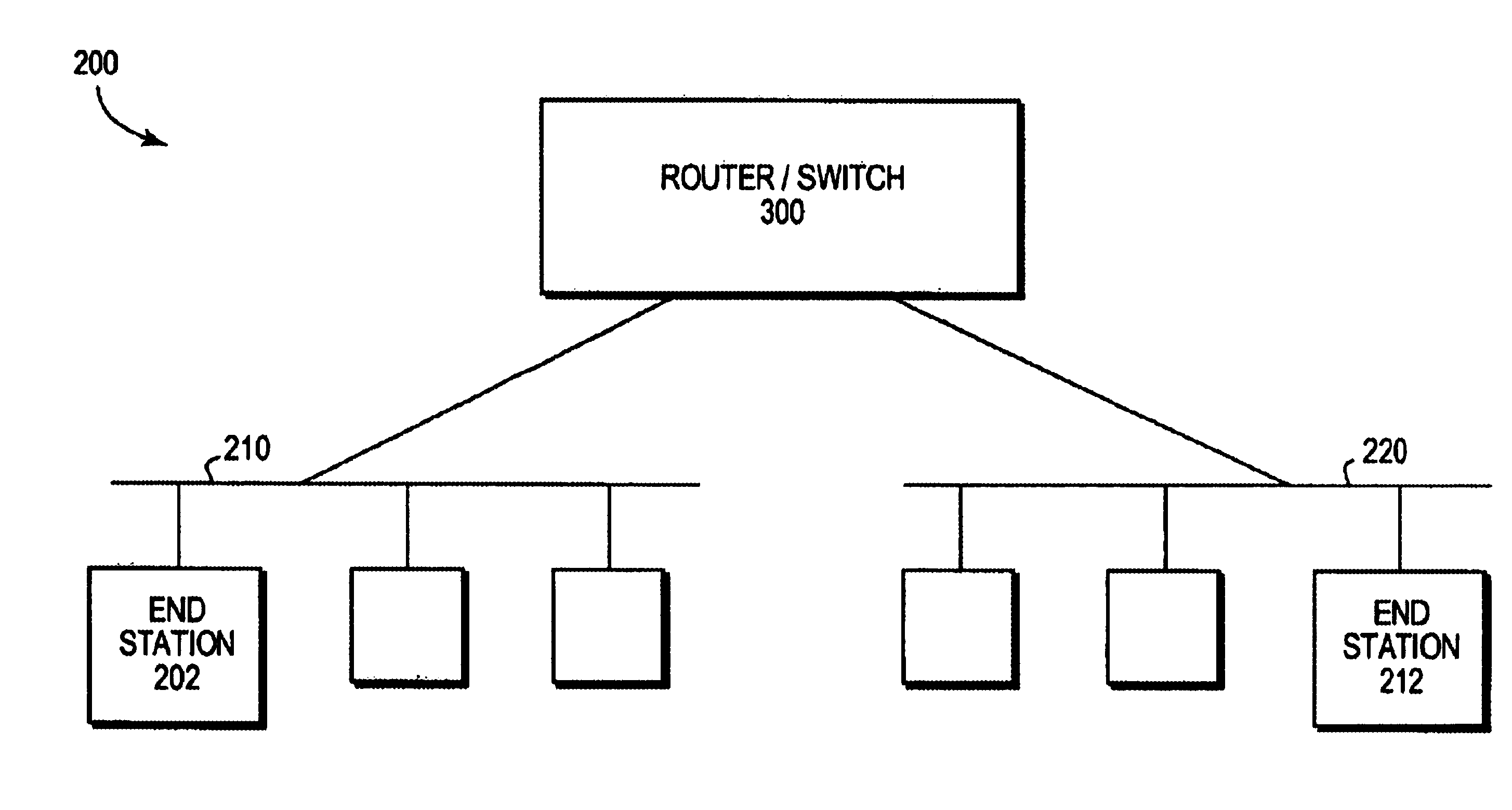
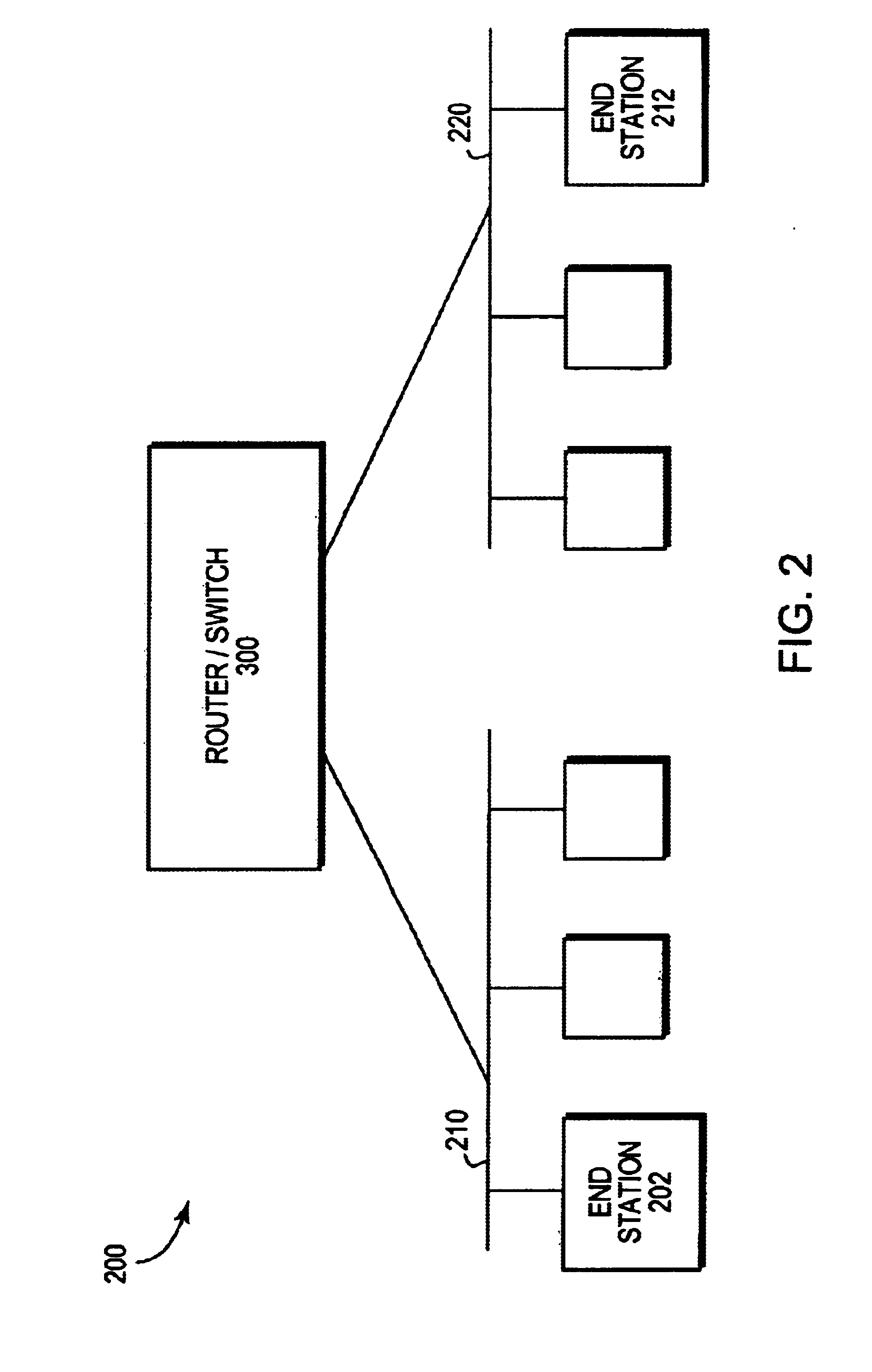
[0028]FIG. 2 is a block diagram of a computer network 200 comprising a collection of interconnected communication media and subnetworks attached to a plurality of stations. The stations are typically computers comprising end stations 202, 212 and intermediate station 300. The intermediate station 300 may be a router or a network switch, whereas the end stations 202, 212 may include personal computers or workstations. The subnetworks generally comprise local area networks (LANs) 210 and 220, although the invention may work advantageously with other communication media configurations such as point-to-point network links. Communication among the stations of the network is typically effected by exchanging discrete data packets or frames between the communicating nodes according to a predefined protocol. For the illustrative embodiment described herein, the predefined protocol is the Internet protocol (IP), although the invention could be implemented with other protocols, such as the Int...


PUM


Abstract

An encryption mechanism tightly-couples hardware data encryption functions with software-based protocol decode processing within a pipelined processor of a programmable processing engine. Tight-coupling is achieved by a micro-architecture of the pipelined processor that allows encryption functions to be accessed as a novel encryption execution unit of the processor. Such coupling substantially reduces the latency associated with conventional hardware / software interfaces.

Description

BACKGROUND OF THE INVENTION[0001]The invention relates generally to data encryption and, more specifically, to a technique for constructing high-performance network systems that have data encryption capabilities.BACKGROUND OF THE INVENTION[0002]Computer architecture generally defines the functional operation, including the flow of information and control, among individual hardware units of a computer. One such hardware unit is the processor or processing engine which contains arithmetic and logic processing circuits organized as a set of data paths. In some implementations, the data path circuits may be configured as a processor having internal registers for use with operations that are defined by a set of instructions. The instructions are typically stored in an instruction memory and specify a set of hardware functions that are available on the processor. When implementing these functions, the CPU generally processes “transient” data residing in a data memory in accordance with th...

Claims


Application Information

Patent Timeline
Patent Type & Authority Patents(United States)
IPC IPC(8): H04L9/00G06F9/30G06F9/38G06F21/00H04L29/06
CPCG06F9/30003G06F9/3877G06F9/3885G06F9/3895G06F21/72H04L63/0428
Inventor KERR, DARRENMARSHALL, JOHN WILLIAM
Owner CISCO TECH INC
Learn More