Pixellated micro-columnar films scintillator

a micro-columnar film and scintillator technology, applied in the direction of optical radiation measurement, radiation controlled devices, instruments, etc., can solve the problems of limited dynamic range, limited contrast sensitivity, significant inherent limitations of film-screen techniques, etc., to reduce optical crosstalk, increase efficiency, and reduce optical crosstalk

Inactive Publication Date: 2005-07-26
RADIATION MONITORING DEVICES
View PDF5 Cites 58 Cited by
  • Summary
  • Abstract
  • Description
  • Claims
  • Application Information

AI Technical Summary

Benefits of technology

[0006]The present invention addresses the above-identified needs by providing an apparatus for an enhanced imaging sensor consisting of micro pixellated scintillator for x-ray imaging comprising a microcolumnar scintillator film in contact with a substrate wherein the micro columnar scintillator film is formed from a doped scintillator material. According to the invention, the micro columnar scintillator film is subdivided into arrays of optically independent pixels having interpixel gaps. These optically independent pixels channel detectable light to a detector element thereby reducing optical crosstalk between the pixels providing for an x-ray converter capable of increasing efficiency without the associated loss of spatial resolution.
[0007]The pixellation of the micro columnar scintillator film forms wedge shaped gaps that are filled with a reflective or refractive dielectric material that substantially reduces optical cross talk between the pixels. Additionally, after the pixellation of the micro columnar scintillator film the film is redoped with a doping compound allowing for improved detective quantum efficiency of the resulting mammography detector.
[0008]The scintillation light produced by the X-ray interaction is channeled within the micro columnar scintillation film via total internal reflection. The light that escapes channeling is confined within a pixel formed by laser ablation, resulting in significant reduction in the lateral light spread and hence the glare in the image. Thus, the micro-columnar structure of the film enhances resolution at high spatial frequencies, which is critical for defining shapes of microcalcifications, and laser pixellation enhances the overall image contrast. A significant advantage of the inventive method is that it allows laser pixellation of very thick scintillator films which offer increased x-ray absorption, thus overcoming the traditional tradeoff between detection efficiency and resolution.

Problems solved by technology

Film-screen technique has significant inherent limitations.
Other well-known shortcomings of film-screen are its limited dynamic range, limited contrast sensitivity, high noise to signal ratio and lack of convenient options for post-processing images.
An added difficulty with film-screen mammography is the logistics of multiple expert opinions, as mailing of films to radiologists for consultation is time consuming and impractical.
Until recently, digital mammography was limited to small field devices for stereotactic localization, core biopsy, and spot compression view.
Unfortunately, in spite of its potential, recent results from clinical trials suggest that current digital mammography is only equivalent to film-screen.
One component that presently limits the performance is the scintillator converter.
Using conventional screens involves a fundamental tradeoff between increasing thickness (and hence efficiency) and decreasing spatial resolution (due to lateral light spreading).

Method used


Image

  • Pixellated micro-columnar films scintillator
  • Pixellated micro-columnar films scintillator
  • Pixellated micro-columnar films scintillator

Examples


example 1

Vapor Deposition

[0023]In a first illustrative embodiment microcolumnar scintillation film material has column diameters in the range of 3 to 5 μm. In this embodiment columns were formed from thallium doped cesium iodide (“CsI:Tl”) that was deposited on a suitable substrate. Film deposition was performed by vapor deposition using high vacuum thermal evaporation from a localized source onto the substrates undergoing planetary rotation during vapor deposition. A thermal evaporator having a planetary system fitted with multiple planets was used.

[0024]During thermal deposition the substrate temperature was maintained at approximately 150 C using a computer controlled halogen lamp heater system (Model QLH0500, Kurt Lesker Company). The evaporation chamber was pumped to a pressure of 5×10⁻⁷ torr prior to deposition and the film growth was monitored and controlled using a closed-loop quartz thickness monitor system.

[0025]To enhance scintillation efficiency, Tl activator concentration in vap...

example 2

Sputter Deposition

[0038]In an alternative illustrative embodiment sputter deposition of CsI:Tl was accomplished by using a planar magnetron sputtering deposition system (Kurt Lesker). Prior to the sputtering process, a high vacuum of 10−7 torr was obtained using a cryogenic pump (oil vapor free) attached to the process chamber. The process chamber contained a substrate holder that was rotated at a speed of approximately 20 rpm to improve the uniformity of the film. A halogen light heater (Model QLH-SPLI, Kurt Lesker Company) was attached to the back side of the substrate holder to maintain substrate temperature at approximately 270° C. during the sputtering process.

[0039]In this alternative illustrative embodiment commercially available crystalline CsI:Tl targets were used for sputter deposition. To provide optimum material usage and improved deposition rates, the target design was modified to allow the application of high sputtering power while offering low thermal resistance. The ...

example 3

Post Pixellation Coatings

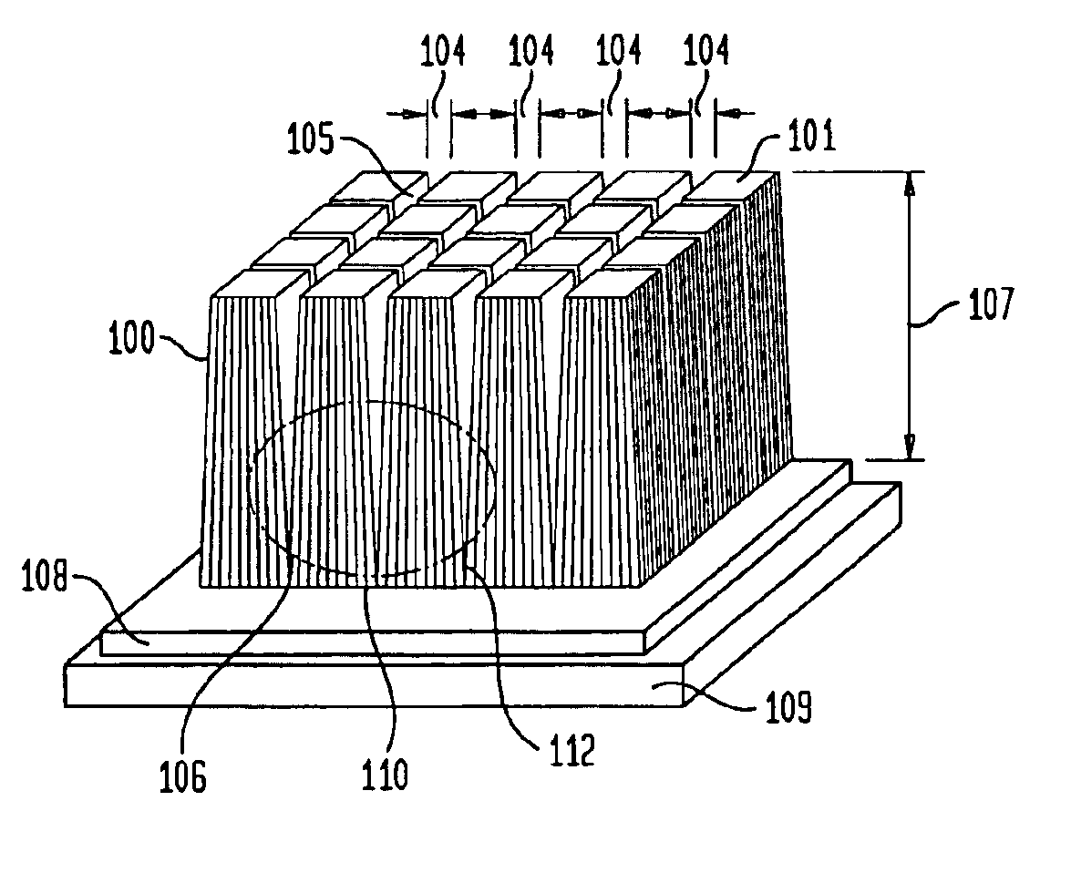
[0042]Once the micro columnar scintillation film material is pixellated the post pixellated micro columnar scintillation film material is coated. The post pixellation coatings enhance the light collection efficiency of the screen, prevent the inter-pixel light from spreading, and protect the micro columnar scintillation film material from moisture and mechanical damage during normal handling. It has been observed that the pixellated screens show loss of light output beyond what is expected based on the loss of screen fill factor. Pixellated films show approximately 55% light output compared to non-pixellated films. Total gain in the light output after SiO coating (compared to pixellated but uncoated film) varied between 15% to 25%. Therefore, laser pixellated screens coated with SiO showed approximately 63% to 68% light output of a non-pixellated and un-processed CsI:Tl screen. Further enhancement of light collection efficiency of the pixellated screen can b...


PUM

PropertyMeasurementUnit
sizeaaaaaaaaaa
widthaaaaaaaaaa
sizeaaaaaaaaaa

Abstract

A method of fabricating an apparatus for an enhanced imaging sensor consisting of pixellated micro columnar scintillation film material for x-ray imaging comprising a scintillation substrate and a micro columnar scintillation film material in contact with the scintillation substrate. The micro columnar scintillation film material is formed from a doped scintillator material. According to the invention, the micro columnar scintillation film material is subdivided into arrays of optically independent pixels having interpixel gaps between the optically independent pixels. These optically independent pixels channel detectable light to a detector element thereby reducing optical crosstalk between the pixels providing for an X-ray converter capable of increasing efficiency without the associated loss of spatial resolution. The interpixel gaps are further filled with a dielectric and or reflective material to substantially reduce optical crosstalk and enhance light collection efficiency.

Description

FIELD OF THE INVENTION[0001]This invention is drawn to a pixellated micro-columnar film scintillator for X-ray imaging with the pixellation resulting in enhanced image contrast. In one embodiment the material of the scintillator is micro-columnar film vapor deposited upon a substrate and pixellated.BACKGROUND OF INVENTION[0002]The World Health Organization's (WHO) International Agency for Research on Cancer (IARC), in Lyon, France, estimates that more than 150,000 women worldwide die of breast cancer each year. During 1999 breast cancer accounted for 29% of all new cancer related cases and 16% of cancer-related deaths in the women population in the United States alone. It has been recognized that treatment effectiveness strongly depends upon early detection and that the x-ray mammography is the only valid and established screening test procedure for detecting early-stage, clinically occult, breast cancer.[0003]Presently virtually all routine clinical x-ray imaging of the breast is p...

Claims


Application Information

Patent Timeline
Patent Type & Authority Patents(United States)
IPC IPC(8): G21K4/00
CPCG21K4/00
Inventor NAGARKAR, VIVEK V.TIPNIS, SAMEER V.
Owner RADIATION MONITORING DEVICES
Why Eureka
Try Eureka