Eureka AIR delivers breakthrough ideas for toughest innovation challenges, trusted by R&D personnel around the world.

Ultraviolet method of embedding structures in photocerams

a technology of photoceramics and ultraviolet light, applied in the field of microfabrication of glass ceramics, can solve the problems of not always optimal materials for use in some mems applications, the current process cannot be used to create potentially useful three-dimensional photoceramics, and the disadvantage of two-dimensional processing steps in microelectromechanical systems (mems) to form three-dimensional structures

Inactive Publication Date: 2005-08-23
THE AEROSPACE CORPORATION
View PDF9 Cites 41 Cited by
  • Summary
  • Abstract
  • Description
  • Claims
  • Application Information

AI Technical Summary

Benefits of technology

[0013]The method is a direct write three dimensional volumetric lithography method for selective removal of the embedded photoceram material. The method is photon efficient in the sense that the laser must only provide the energy to form a latent image. It does not need to provide the energy to break atomic bonds and remove unwanted material from the workpiece. Direct write tools, such as computer aided manufacturing programs and fixtures coupled to a pulsed UV laser are used in a micromachining station for rapid batch processing and enhanced depth control. The pattern exposure and dissolving steps can be done across an entire wafer for batch processing. These and other advantages will become more apparent from the following detailed description of the preferred embodiment.

Problems solved by technology

However a preferred material, silicate glass, is not used often because of the difficulty of microfabricating embedded fluid channels and the difficulty of sealing open trench surface channels.
Microelectromechanical Systems (MEMS) typically disadvantageously uses two dimensional processing steps to form three dimensional structures in bulk materials.
However, semiconductors are not always optimal materials for use in some MEMS applications.
Current processes can not be used to create potentially useful three dimensional photoceramic structures such as a simple buried tunnel in a monolithic material.
Furthermore, photolithographic processing of a monolithic material is not amenable to undercutting of patterned structures in a way that leaves anchored or suspended structures.
Soaking the sample in an HF solution results in dissolution of the exposed regions leaving unexposed patterned structures.
However, the UV exposure is commonly directed to fabricating structures showing surface relief and is unsuitable for dissolving the crystalline material embedded within the workpiece.
However, embedded structures are difficult to obtain because lamp spectra is too broad and weak for effective exposure within the workpiece.
Focusing the lamp with broad spectrum light is also unsuitable for forming a stacked embedded structure because regions above and below the volume at the depth of focus may also accumulate a dose, and over subsequent exposure operations would convert to the crystalline phase preventing the formation of precise three dimensional embedded structures.

Method used


Image

  • Ultraviolet method of embedding structures in photocerams
  • Ultraviolet method of embedding structures in photocerams
  • Ultraviolet method of embedding structures in photocerams

Examples


Embodiment Construction

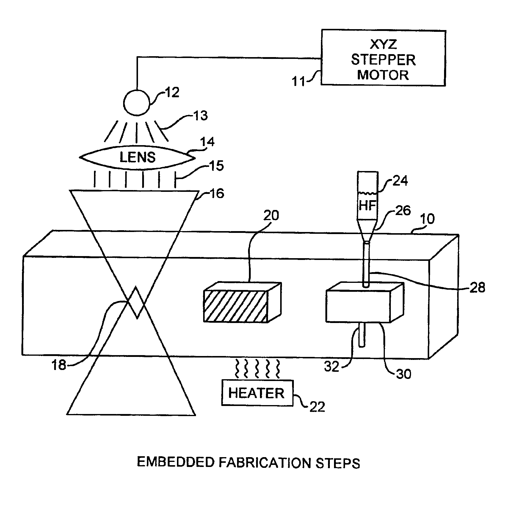
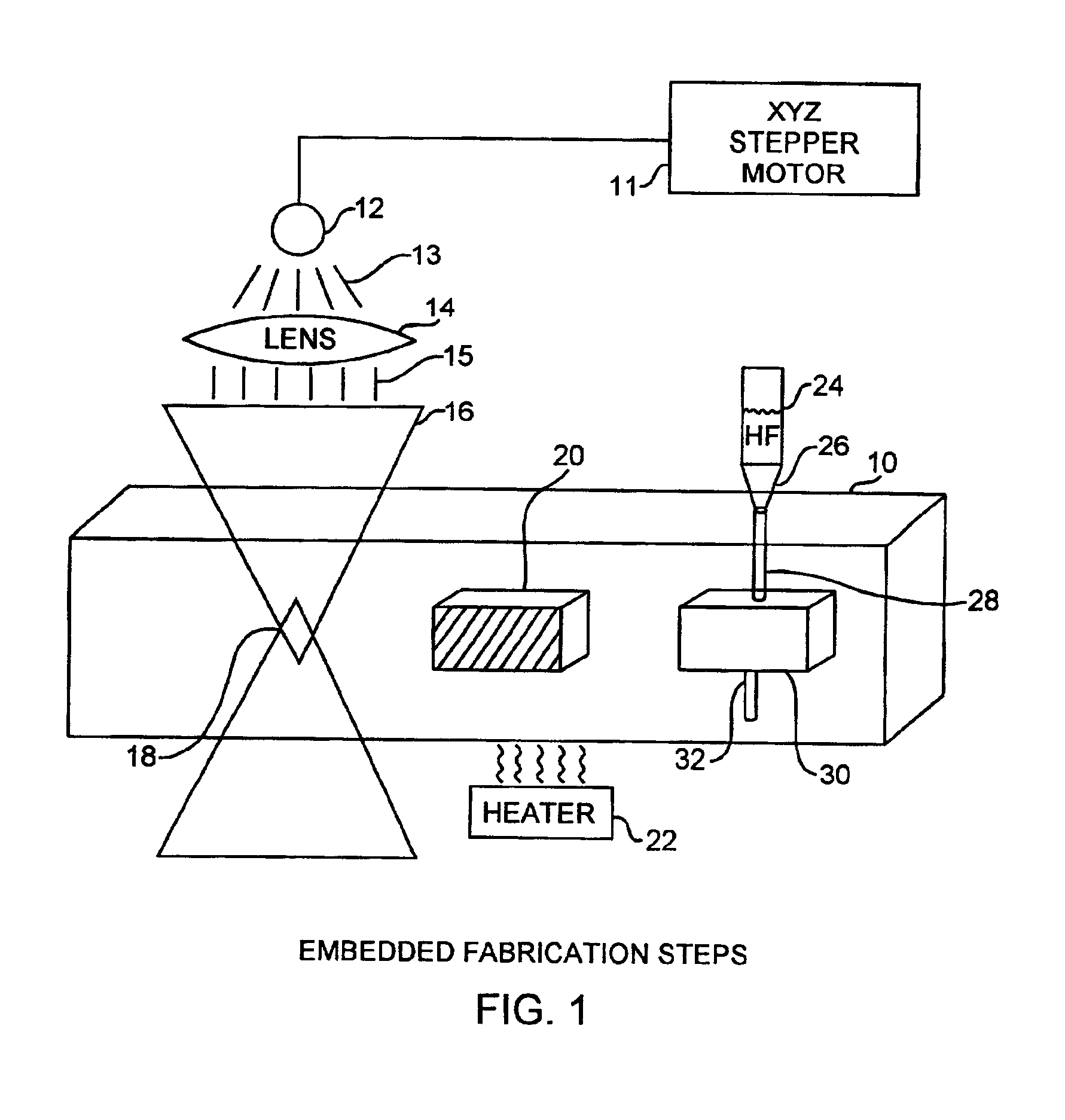
[0017]An embodiment of the invention is described with reference to the figures using reference designations as shown in the figures. Referring to the Figures, a photoceram material sample 10 is moved using a stepper motor 11 relative to a pulsed ultraviolet (UV) laser 12 radiating pulsed laser light 13 through a microscope object lens 14 providing refracted light 15 that is focused into a focused beam 16 having a focal region 18 within the sample 10. Alternatively, the photoceram material sample 10 can remain fixed and the focused laser beam 16 can be made to move. The outcome is the same. The sample material is preferably Foturan, but other photostructurable photocerams may be used. The focal region 18 has a beam waist that partially defines a focal depth into the sample 10. The sample 10 is shown having a exposed focal volumetric region 20 through which the focal region 18 had been previously stepped. The volumetric region 20 defines a focal volume of the material that has receiv...


PUM

PropertyMeasurementUnit
Wavelengthaaaaaaaaaa
Volumeaaaaaaaaaa

Abstract

A laser direct write method creates true three dimensional structures within photocerams using an focused pulsed ultraviolet laser with a wavelength in a weakly absorbing region of the photoceram material. A critical dose of focused laser UV light selectively exposes embedded volumes of the material for subsequent selective etching. The photoceram material exposure is nonlinear with the laser fluence and the critical dose depends on the square of the per shot fluence and the number of pulses. The laser light is focused to a focal depth for selective volumetric exposure of the material within a focal volume within the remaining collateral volumes that is critically dosed for selecting etching and batch fabrication of highly defined embedded structures.

Description

FIELD OF THE INVENTION[0001]The invention relates to the field of microfabrication of glass ceramics. More particularly, the present invention relates to the manufacture of structure within photoactivable glasses and ceramics.BACKGROUND OF THE INVENTION[0002]The miniaturization processes of analytical microsystem instruments for chemical and biological assay are well known. For many microsystem applications, glass is the preferred material over metal, silicon, and some plastics, because of its transparency and intertness to biological contamination and to many caustic chemicals. However a preferred material, silicate glass, is not used often because of the difficulty of microfabricating embedded fluid channels and the difficulty of sealing open trench surface channels. Typically, fabrication of a channel or a tunnel requires cutting a trench out of a workpiece and sealing this trench with another piece of glass that is aligned and bonded on top of the open trench. A processing step ...

Claims


Application Information

Patent Timeline
IPC IPC(8): C03C23/00B44C1/22B81C1/00
CPCB44C1/227B44C1/228B81C1/00492C03C23/0025B81C2201/0133B81C2201/0143
Inventor HELVAJIAN, HENRYFUQUA, PETER D.HANSEN, WILLIAM W.
Owner THE AEROSPACE CORPORATION
Why Eureka
Eureka Blog
Learn More