a) Structural Considerations Of Post Component,
b) Construction Of Cantilevered Structural Support Systems Such As But Not Limited To Highway Guardrail Structural Systems, Focusing On The Post Component,
c) Failure Mode Design Concerns On Guardrail Post Component.
a) Structural Considerations Of Post Component The present Invention relates to and addresses concerns inherent to the present art's use of “hot-rolled” steel structural Wide-
Flange shapes or “cold-rolled” steel Channel shapes as a highway guardrail post. The following are two such structural considerations required of a Guardrail Post component.
First, the most widely used highway guardrail
system is the “strong-post” design. Strong-post guardrail systems
resist impacting vehicles in a rigid manner providing for little deflection of the cantilevered support post components. The present Invention provides for equal or greater resistance to lateral loads.
Second, the present Invention provides for equal or greater “spade” interaction with the standard soil-matrixes compared to the present art. The present art Strong-post guardrail systems depend on in-situ soil
matrix strength to carry design-intended loads without
structural failure. Expanding on the above issues, laterally loaded
shallow foundation piles, such as permanent retaining walls, permanent sea walls, permanent and / or temporary trench walls, underground support structures, and similar
structural system components such as guardrail posts tend to be designed as cantilevers. That is, one end of the
pile or post is considered structurally “fixed” and the other end is structurally “not-fixed” or “free-to-rotate” or “deflect-under-load”; or the “not-fixed” end is allowed to deflect when under design loadings. In the case of a cantilevered
retaining wall component, the
design load is usually applied over the length of the
pile with higher design loadings at the
pile's “fixed” end. The
design load usually tapers off as one moves toward the “not-fixed” end of the pile. In the case of a “strong-post” guardrail
system, the
design load is usually a “point-load” applied via the W-beam rail component thru the “spacer-block” to the “not-fixed” end (in normal guardrail applications the “not fixed” end is the TOP of the post). In any of these case loadings, or similar loadings, the face of the pile or post facing toward the loadings tend to be in “tension” when under design loads. The opposite face of the pile or post tends to be in “compression” when design loads are applied. To maintain
structural integrity, the pile or post must transfer “shear” between the opposing faces (tensile / compressive) without significant change in distance between the faces. Failure of the soil matrix to
resist the design lateral loadings is usually a result of either inferior soil conditions for the design loads in question, or failure of the post's compressive face to fully develop the strength of the soil matrix due to less than optimal “spade” dimensionality aspects of the post's width of “face” against the in-situ soil matrix in question. (failure of the soil matrix in contact with the post's tensile face should be considered but is usually rare in “short” piles such as guardrail posts as the soil-matrix in question tends to be more structurally strong as one approaches the roadway
bedding). Quoting from Reference #1, pages 8 & 9: “Precisely predicting potential ground movements . . . at a specific site and estimating the effects of [ . . . ] the response and any site / structure interaction are conjectures of ethereal proportions. Determining or controlling the conditions of a specific
soil mass is a highly approximate exercise. Precisely determining the dimensional changes of complex masses of construction due to thermal or
moisture variation is not possible.” The post's “top” must retain its
structural integrity so as to fully develop the load transfer from the highway guardrail
system's “spacer-block”.
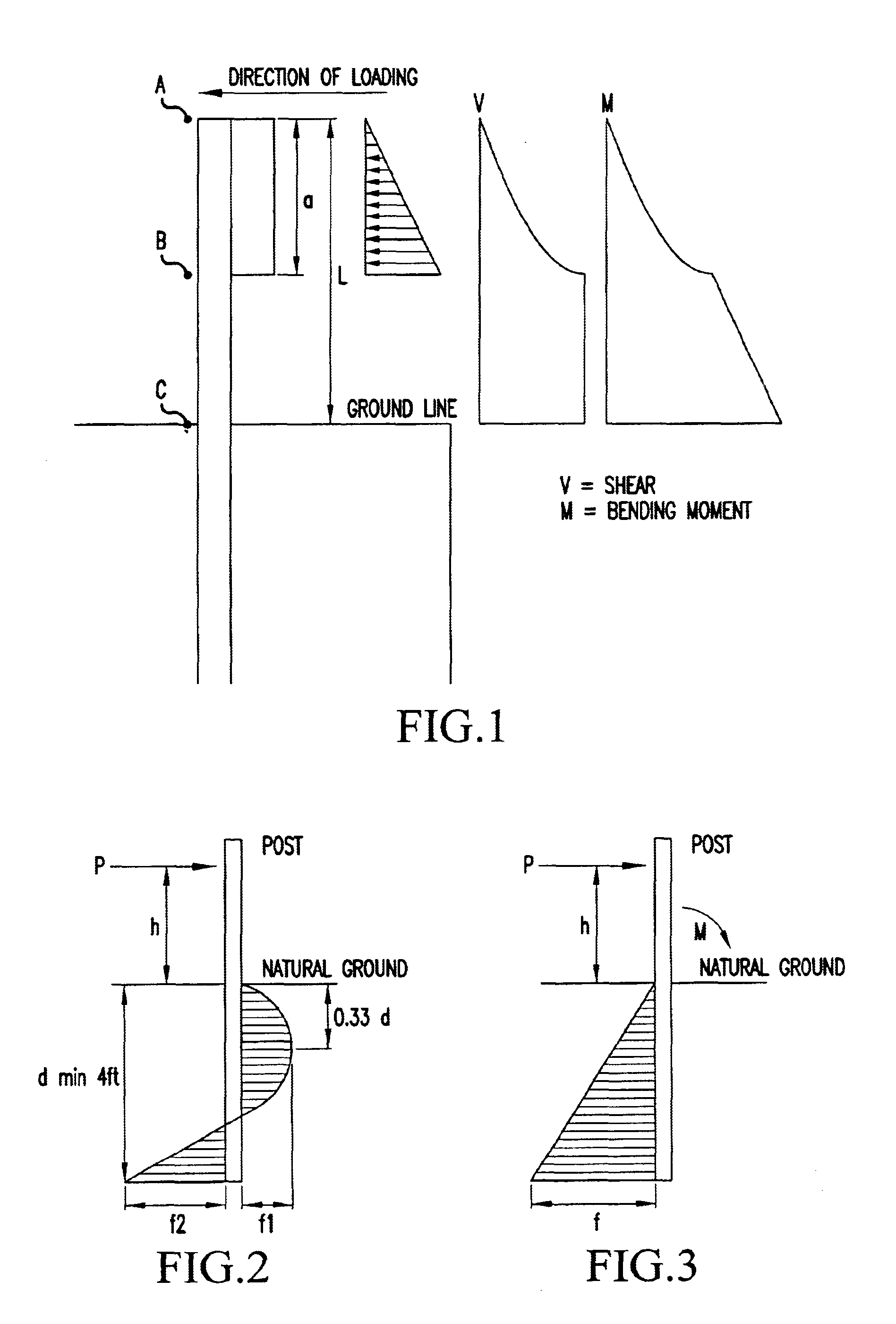
b) Construction Of Cantilevered Structural Support Systems Such As But Not Limited To Highway Guardrail Structural Systems, Focusing On The Post Component Lateral service loads require a cantilevered structural member such as a highway guardrail post to transfer the
service load from its “not-fixed(A)” end to its “fixed(C)” end. In the process, the structural requirements increase as the load moves from “A” to “B”. The “strong-post” guardrail system is a cantilevered, moment-resistive frame. Quoting from Reference #1, page 92, “In most cases rigid frames are actually the most flexible of the basic types of lateral resistive systems. This deformation character, together with the required
ductility, makes the
rigid frame a structure that absorbs energy loading through deformation as well as through its sheer brute strength. The net effect is that the structure actually works less hard in force resistance because its deformation tends to soften the loading. This is somewhat like rolling with a punch instead of bracing oneself to take it head on.”
c) Failure Mode Design Concerns On Guardrail Post Component. There are two load cases and two time-sequences, on the subject of failure-mode, that need to be addressed, individually and in combination. (It is assumed that the applied loadings and their nature would be properly investigated to avoid issues such as, but not limited to “shear-punch-thru”.) The first load case is “static” loadings. The second load case is “dynamic”. The first time-sequence is “constant”. The second time-sequence is “intermittent”. Most
retaining wall loadings are of a “static” nature where the loadings are “constant”. That said, retaining walls used near highways and / or in applications such as of bridge-abutments tend to also experience “dynamic” loadings from passing vehicles of an “intermittent” timing nature. In all these cases, when the material is a commonly used structural
metal such as steel, it is desirable that the design of the structural member in question be such that when loaded to the point of failure, that said failure not occur in compression and / or shear as these failure
modes tend to not give visible ad / or audible notice of approaching
structural failure. Tensile failure usually results in elongation on the tensile face or “bowing out” of the structural
support system allowing for some visible signs of impending
structural failure. In addition, tensile failure of aluminum or steel is usually in conjunction with alerting
noise-generation. In the special case of
metal guardrail post applications, the desired failure-mode may, in fact, be localized buckling of either the compressive face or the interface region of the compressive face and web. This type of structural failure allows for reduced
snagging potential in the event that the impacting vehicle has “laid-back” the line of rail to the extent that the vehicle's wheel would otherwise get “caught” on a post which structurally failed in tension. A catastrophic structural post failure also allows for a transfer of the impacting vehicle's load to be distributed to the up-
stream and down-
stream posts before the vehicle actually encounters the failed post thereby “
softening” the nearby posts'
initial load times. Use of wood or wood-like materials for post construction requires other structural considerations. Quoting from Reference #4, page 3-22 “When wood specimens are loaded in bending, the portion of the wood on one side of the
neutral axis is stressed in tension parallel to grain, while the other side is stressed in compression parallel to grain . . . ”“Bending also produces
horizontal shear parallel to grain, and compression perpendicular to grain at the supports. A common failure sequence in simple bending is the formation of minute compression failures followed by the development of macroscopic compression wrinkles. This effectively results in a sectional increase in the compression zone and a section decrease in the tension zone, which is eventually followed by tensile failure.” Use of composite wood-steel, or similar configurations, requires identification of failure-mode
mechanics to ensure intentional “lay-back” and / or structural failure of the post for proper lateral-resistant structural system response.
While the failure-mode of a typical cantilevered
retaining wall is relatively simple, the required failure-mode for the present art standard highway guardrail post is more complex.
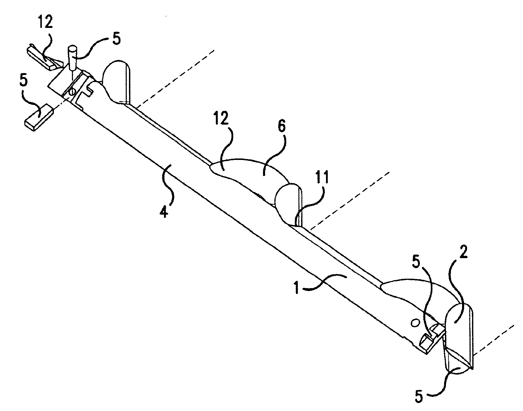
The present art, because only half of the block can be structurally loaded due to the center-position of the post-bolt, does not allow the full development, thru composite action, of the structural strength of the block.
The present art primary failure mode design concern is that the block should keep and maintain the design distance between the post component and the rail component for the design loads intended.
When loadings in excess of design loads are encountered, the block should structurally fail only after a structural failure of the post.
That said, in cases of significant lateral loadings greater than design loads, a block should structurally fail once its companion post element has deformed and / or displaced and has assumed a position bent back and in the proximity of the ground-line.
If block separation does not occur easily the vertical aspect or height of the rail element may be reduced resulting in a greater probably of the impacting vehicle rolling over the rail.
A secondary failure mode design concern is that the block should provide torsion-resistance by structurally transferring loads to the next post component in line.
Another secondary failure mode design concern is that the block should provide help in keeping the rail component splice region in-plane.
At issue is the use of the W-beam rail.
Unfortunately, the
present day passenger vehicle with the collapsible, shock absorbing front fenders and bumpers, when impacting a standard W-beam, can act to “ramp” the vehicle either up-and-over or down-and-under the W-beam rail until the rigid-structural-components of the passenger compartment engages the rail component.
This condition potentially results in pieces of the vehicle's
fender and / or bumper protruding past the
vertical plane of the W-beam rail and
snagging on the standard block portions that extend above and below the W-beam rail unit and / or
snagging on the post unit even in low impacts where the guardrail is still upright (not laid-back as a result of a high-
energy impact or weak soil foundation conditions).
This overlapping adds significant stiffness to this location.
Shear-tear failure frequently occurs in this region of the W-beam.
Failure usually occurs when an impacting vehicle deflects the guardrail line resulting in application of torque to the nearby posts, thru the post-
bolt connection.
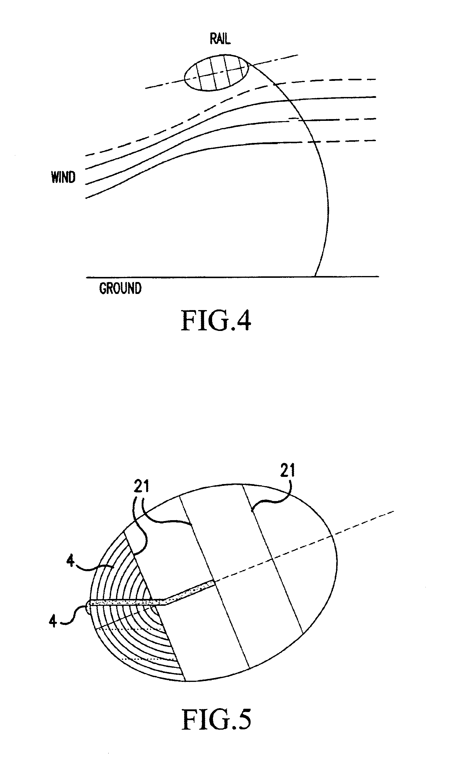
Tests have shown that the present art's use of the W-beam is not aerodynamic and is a leading cause of airborne solids accumulation on roadway surfaces such as
snow or sand.
Unfortunately, the
present day passenger vehicle with the collapsible, shock absorbing front fenders and bumpers, when impacting a standard W-beam, can act to “ramp” the vehicle either up-and-over or down-and-under the W-beam rail until the rigid-structural-components of the passenger compartment engages the rail component.
This condition potentially results in pieces of the vehicle's
fender and / or bumper protruding past the
vertical plane of the W-beam rail and snagging on the standard block portions that extend above and below the W-beam rail unit and / or snagging on the post unit even in low impacts where the guardrail is still upright (not laid-back as a result of a high-
energy impact or weak soil foundation conditions).
The present Invention's aerodynamic shape enhances the rail's ability to develop a crease in an impacting vehicle's
crash-zone thereby holding the vehicle and not allowing the vehicle to ramp over or under the rail element.

