High frequency plasma source

a plasma source and high frequency technology, applied in the field of high frequency plasma sources, can solve the problems of low plasma density, insufficient particle current, and large ion energy distribution, and achieve the effects of increasing the versatility, functionality and efficiency of plasma sources, high plasma densities, and high degrees of dissociation and ionization

Inactive Publication Date: 2005-08-30
CCR GMBH BESCHICHTUNGSTECH
View PDF6 Cites 19 Cited by
  • Summary
  • Abstract
  • Description
  • Claims
  • Application Information

AI Technical Summary

Benefits of technology

[0014]This invention concerns the task to increase the versatility, functionality and efficiency of plasma sources, i.e. to make ion energy and ion ...

Problems solved by technology

The disadvantage of capacitively coupled high frequency systems is the low plasma density, which is a consequence of the inefficient coupling of the high frequency power into the plasma.
For many applications which demand a high energy ion dominant process this particle current is not sufficient.
Further disadvantages of conventional high frequency plasma sources are the broad ion energy distribution, low growth rates and the dependency of other process parameters on the specific environment.
One problem of conventional plasma sources is that ion energy and ion current density are not adjustable i...

Method used


Image

  • High frequency plasma source
  • High frequency plasma source
  • High frequency plasma source

Examples


Embodiment Construction

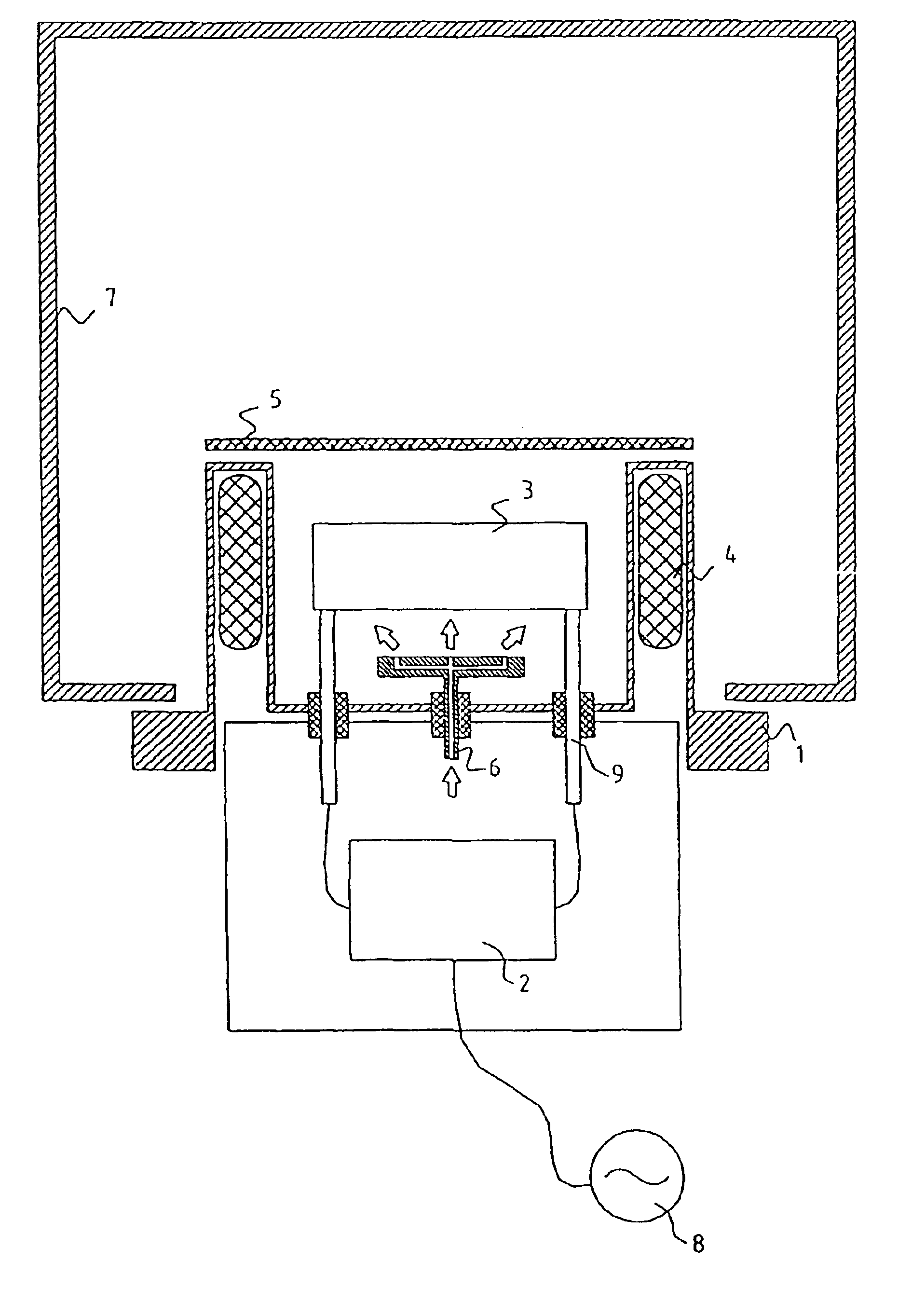
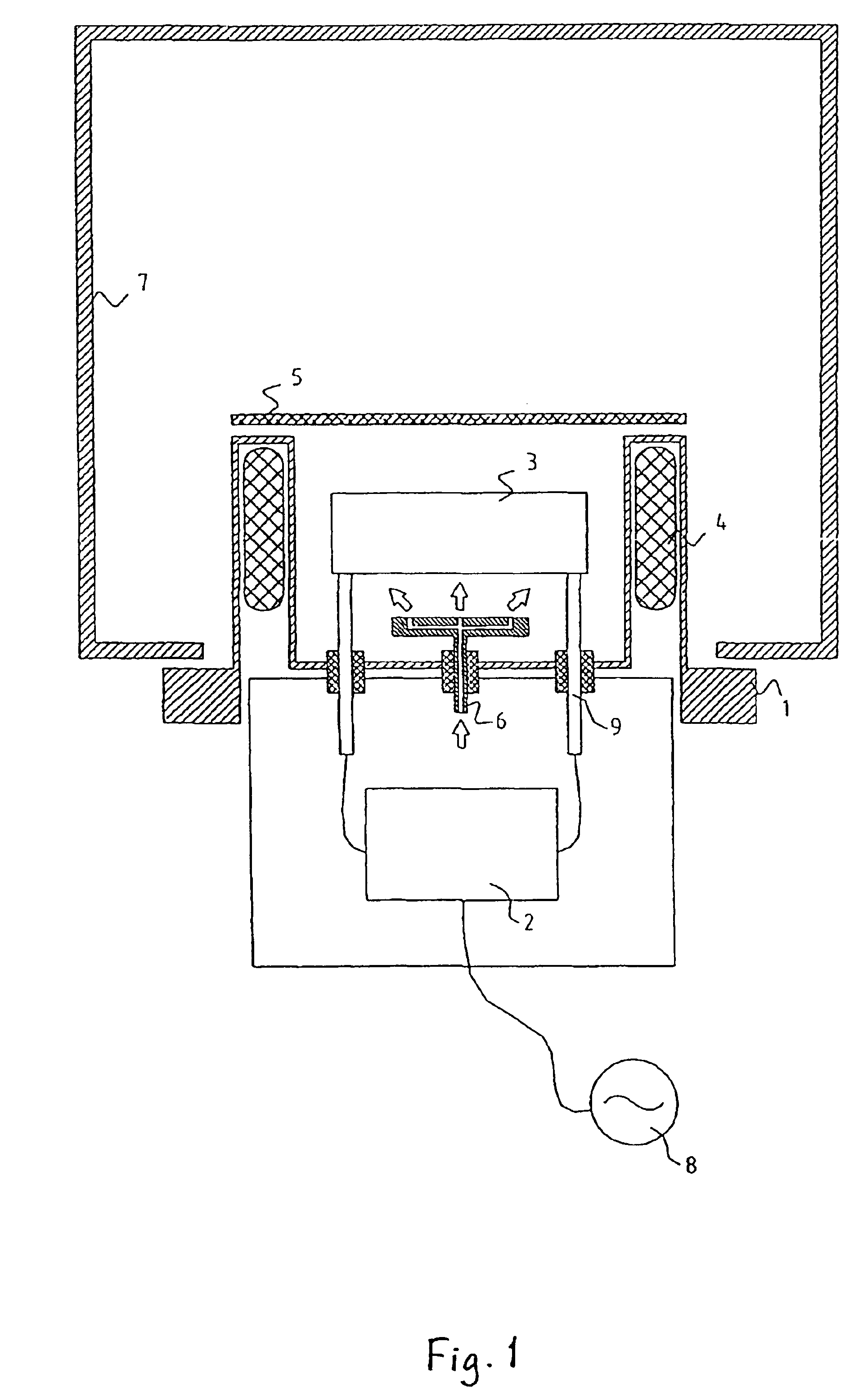
[0036]The principal assembly of the plasma source is shown in FIG. 1. The plasma source is assembled of various main components including a mounting element 1, on which an arrangement of various magnetic field coils 4 to generate a transverse magnetic field, a plasma beam extraction unit 5 to extract the plasma beam and a gas distribution system 6 are placed. Additionally in the interior of the plasma source there is a high frequency matching network 2 to match the impedance with the belonging excitation electrode 3 to generate the plasma connected to the mounting element 1. The excitation electrode 3 is situated inside a vacuum defined by mounting element 1 and an outer wall 7 and connected by vacuum current feed-throughs 9 with the main part of the matching network 2. The working gas is led into the plasma chamber by the gas distribution system 6 through the plasma source. The plasma source represents in its assembled state after tuning of all components a closed unit, which can b...


PUM

PropertyMeasurementUnit
Distanceaaaaaaaaaa
Magnetic fieldaaaaaaaaaa
Sizeaaaaaaaaaa

Abstract

A high frequency plasma source includes a support element, on which a magnetic field coil arrangement, a gas distribution system and a unit for extraction of a plasma beam are arranged. Additionally a high frequency matching network is arranged within the plasma source.

Description

PRIORITY CLAIM[0001]This is a U.S. national stage of application No. PCT / EP01 / 01952, filed on Feb. 21, 2001. Priority is claimed on that application and on the following application(s): Country: Germany, Application No.: 100 08 482.6, Filed: Feb. 24, 2000; Country: Germany, Application No.: 100 08 483.4, Filed: Feb. 24, 2000; Country: Germany, Application No.: 100 08 484.2, Filed: Feb. 24, 2000; Country: Germany, Application No.: 100 08 485.0, Filed: Feb. 24, 2000; and Country: Germany, Application No.: 100 08 486.9, Filed: Feb. 24, 2000.BACKGROUND OF THE INVENTION[0002]1. Field of the Invention[0003]The present invention concerns an apparatus for the efficient excitation of a low pressure gas discharge (plasma). The apparatus generates a highly ionized and charge compensated plasma beam, which is extracted from a very dense low pressure plasma. The properties of the plasma beam (i.e. ion energy, ion current density, composition of the ion beam) can be well controlled and adjusted. ...

Claims


Application Information

Patent Timeline
IPC IPC(8): H01J37/32H01L21/205H01L21/3065H05H1/46
CPCH01J37/32082H01J37/32091H01J37/321H01J37/32183H05H1/46H01J37/32
Inventor WEILER, MANFREDDAHL, ROLAND
Owner CCR GMBH BESCHICHTUNGSTECH
Why Eureka
Try Eureka