
Infrared irradiation

a technology of infrared radiation and irradiation chamber, which is applied in the field of infrared radiation, can solve the problems of large areas of the surface of objects, or even the object as a whole, being unavoidably heated, and it is impossible to begin to dry or fix the applied materials, and achieves the effect of short irradiation times

Inactive Publication Date: 2005-09-06
ADVANCED PHOTONICS INC
View PDF13 Cites 4 Cited by
  • Summary
  • Abstract
  • Description
  • Claims
  • Application Information

AI Technical Summary

Benefits of technology

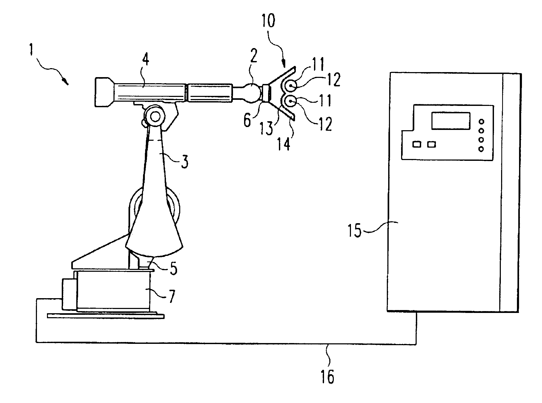
[0010]In accordance with a central idea of the invention, a source of infrared radiation is moved by means of a robot into one or several operating positions, in which radiation is applied to the particular target object. The term “robot” designates industrial robots and similar movable apparatus capable of placing the radiation source in the desired operating position or positions. It is advantageous for the robot to be freely programmable, so that within its operating range it can move to any desired position and, preferably, in each of these positions can aim the radiation source in any desired, freely predeterminable direction.
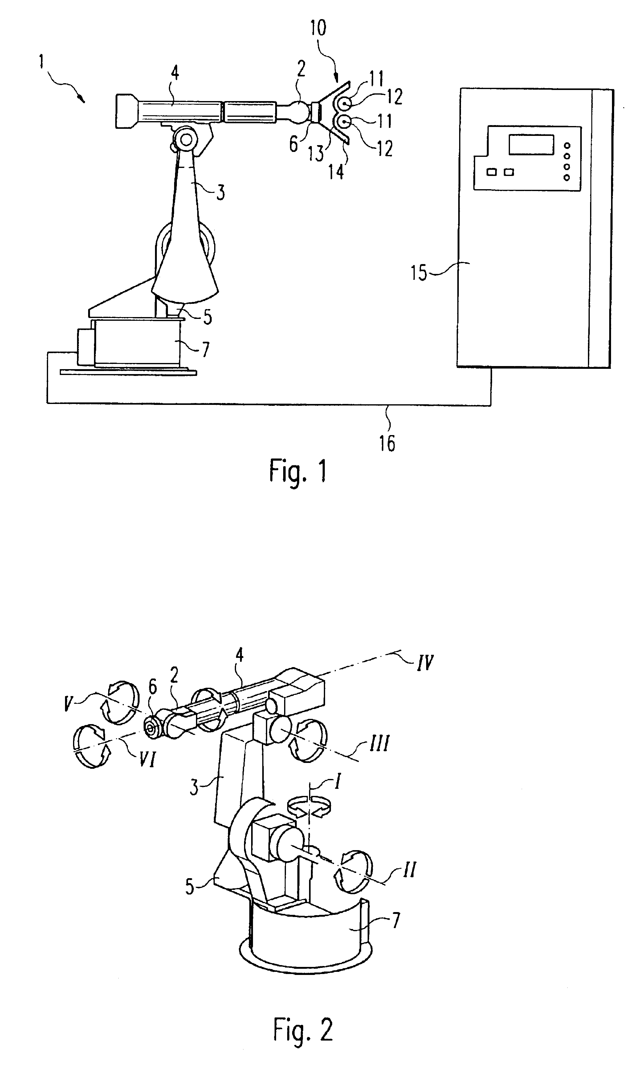
[0013]The robot advantageously comprises a holder to contain the radiation source, in which case the holder is connected by way of a pivotable and / or linearly movable robotronic mechanism to a supporting device that keeps the robot stably at the desired site. In a manner known per se, the robotronic mechanism can in particular be swiveled about several axes, for example six axes. In this way, by combination with a suitable robot controller, the freely predeterminable and arbitrary position and orientation of the radiation source can be approached and established.
[0014]In a further development of the method in accordance with the invention, the radiation source is moved continuously within a range of operating positions, so that the infrared radiation sweeps across one or more surface regions of the target object. The radiation source thus “scans”, so to speak, the surface of the object. By this means even surfaces with the most complicated geometries can be irradiated with a uniform input of energy per unit area. It is also possible, for instance when a coating is being applied to a chassis, to begin the irradiation in one surface region, or in the region of joints, cavities or similar recessed spaces, while at another site material is still being applied. In particular, because of this feature it is no longer necessary to treat the entire surface, i.e. the entire target object or at least large parts thereof, when irradiation or treatment is actually required only in smaller areas of the surface. Hence by means of the invention production times can be shortened and in some circumstances continuous furnaces, irradiation chambers and similar space-consuming equipment can be eliminated.
[0018]It is especially preferred to use infrared radiation in the near infrared, i.e. in the wavelength region between the visible and 1.5 micrometers wavelength. Accordingly, in particular a radiation source is used that has a thermal radiator designed for the emission of electromagnetic radiation at surface temperatures of more than 2000 K, in particular more than 2500 K. Operation at such high surface temperatures offers the advantage that, according to Plank's radiation law, the radiance of the emitted radiation increases about as the fourth power of the absolute surface temperature (provided that the emissivity is approximately independent of temperature). At the high temperatures proposed here, therefore, the amount of energy required for the particular purpose of the irradiation can be transferred to the irradiated object in a short time. Hence it is especially preferred to use radiation sources with thermal radiators that can be operated at surface temperatures of more than 3000 K. In this case the energetic maximum of the emitted radiation is at wavelengths below 1 micrometer. A further advantage of the short irradiation times attainable with appropriately high radiation flux densities lies in the slight degree to which the irradiated object as a whole is heated. That is, the surfaces of the object or the layers disposed on the surface can be heated thoroughly in a short time, which is insufficient for heat to be conducted through the whole body of the object. By adjusting the spectrum of the incident radiation in accordance with the absorption properties of the surface of the target object, or the layers covering that surface, it is even possible to limit the heating to a specified depth. For example, if the absorptance of a surface layer is distinctly lower than 1, but nevertheless because of the thickness of the surface layer almost all the radiant energy is absorbed in the surface layer, then although the surface layer is thoroughly heated, there is no appreciable heating of the underlying layer or layers.

Problems solved by technology

In both the continuous furnaces and the radiation chambers, large areas of the surfaces of objects, or even the object as a whole, are unavoidably heated.
Furthermore, it is impossible to begin to dry or fix the applied materials while the process of application is still underway at other places on the surface of the object.

Method used


Image

  • Infrared irradiation
  • Infrared irradiation

Examples


Embodiment Construction

[0022]The schematic drawing in FIG. 1 shows a robot 1 that carries a halogen radiator 10. Here the robot 1 and the halogen radiator 10 are in the standby position. The robot 1 can move out of this position so as to put the radiator 10 into various operating positions and orient the radiator 10 in such a way that pre-programmed surface regions of a target object (not shown) can be irradiated with a specified radiation flux density and for a specified period of time. The sequence of movements of the robot 1 required for this purpose is controlled by a control unit 15, as is the time during which an electric current is turned on in order to produce the desired amount of infrared radiation. The control unit 15 is connected, by way of a cable comprising control leads 16, to a stand 7 on which the robot 1 is mounted. From there each of the individual control leads runs to its particular connector.

[0023]The robot 1 comprises six axes of rotation, as shown in FIG. 2. Axis 1 is vertically or...


PUM


Abstract

The invention relates to a method and a system for irradiating objects with infrared radiation, in particular in order to dry surface layers and / or fix them in place, wherein a radiation source (10) is moved by means of a robot (1) into one or several operating positions in which the particular target object is irradiated.

Description

BACKGROUND OF THE INVENTION[0001]The invention relates to a method and a system for irradiating objects with infrared radiation, in particular for the purpose of drying surface layers and / or fixing them in position.[0002]For example, a known procedure for the serial lacquering of the surfaces of objects is to transport the objects through a lacquering chamber. This chamber contains a mist of lacquer droplets, which precipitate onto the surfaces of the objects. Subsequently the objects are transported into a drying chamber where the layer of lacquer is dried.[0003]Particularly in the case of objects with irregularly shaped, complicated surfaces it is further known to employ industrial robots that are freely programmable; these can spray nearly uniformly thick layers of lacquer onto the relevant surface regions. By means of the industrial robots it is possible to reach even relatively inaccessible parts of the surface, for instance in the region of recesses, cavities, joints and the l...

Claims


Application Information

Patent Timeline
IPC IPC(8): B05D3/02F26B3/00F26B3/30B05C9/14
CPCB05D3/0263F26B3/30
Inventor BAR, KAI K. O.GAUS, RAINER
Owner ADVANCED PHOTONICS INC
Learn More