However, one drawback to this approach is the
moving parts associated with the required scanning operation.
Such
moving parts inherently limit the ruggedness and portability, for example, of such a device.
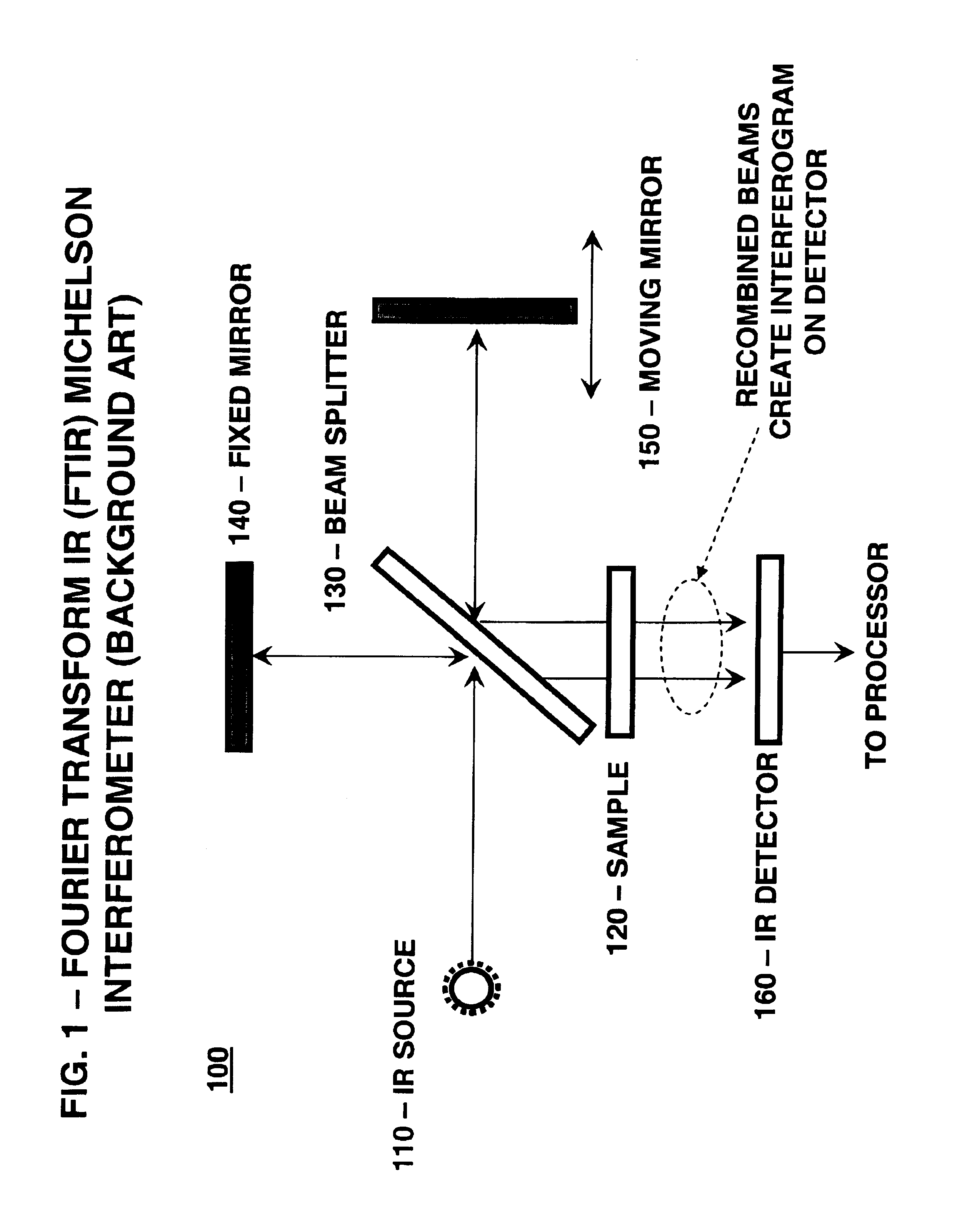
After traveling a different distance than a
reference beam, the second beam and the
reference beam are recombined, and an interference pattern results.
The same technological innovations that have made FT instruments those of choice for a generation of spectroscopists, however, have also made them extremely sensitive to their
operating environment.
For these reasons, FT interferometers are mostly limited to laboratory conditions which require the use of an optical bench to prevent vibration, and which also require stringent environmental controls to control temperature variations that adversely affect the interferogram by thermally inducing
path length differences.
While this type of scanning approach has proven to be workable, the
signal-to-
noise-ratios (SNR) obtainable in some situations often require substantial
signal averaging of multiple interferograms, thus making FTIR systems inherently slower than desired under some circumstances, with reduced speed and potentially lower reliability resulting from the numerous moving parts of these systems.
Otherwise, chemical information is lost if the resolution is too low, as adjacent peaks identified with a particular
chemical bond or vibration state may be “smeared” together and rendered indiscernible if a lower resolution is used.
However, it has become clear that the moving mirror mechanism in a traditional interferometer has limited the design and construction of a more compact and portable FTIR.
The resulting
optical path difference (OPD) between the two
fiber channels due to changes in both the length and the
refractive index of the heated / cooled
fiber caused interference in the combined channel.
However, the interference of two light beams in the optical fibers under different thermal and mechanical conditions turned out to be very complex.
In contrast to the traditional
Michelson interferometer, whose only source of
optical path length difference comes from the geometric
path length resulting from the moving mirror, a
fiber-optic interferometer responds to any mechanical or thermal changes of the
operating environment, which causes a scrambling or loss of the phase information necessary for interference to occur.
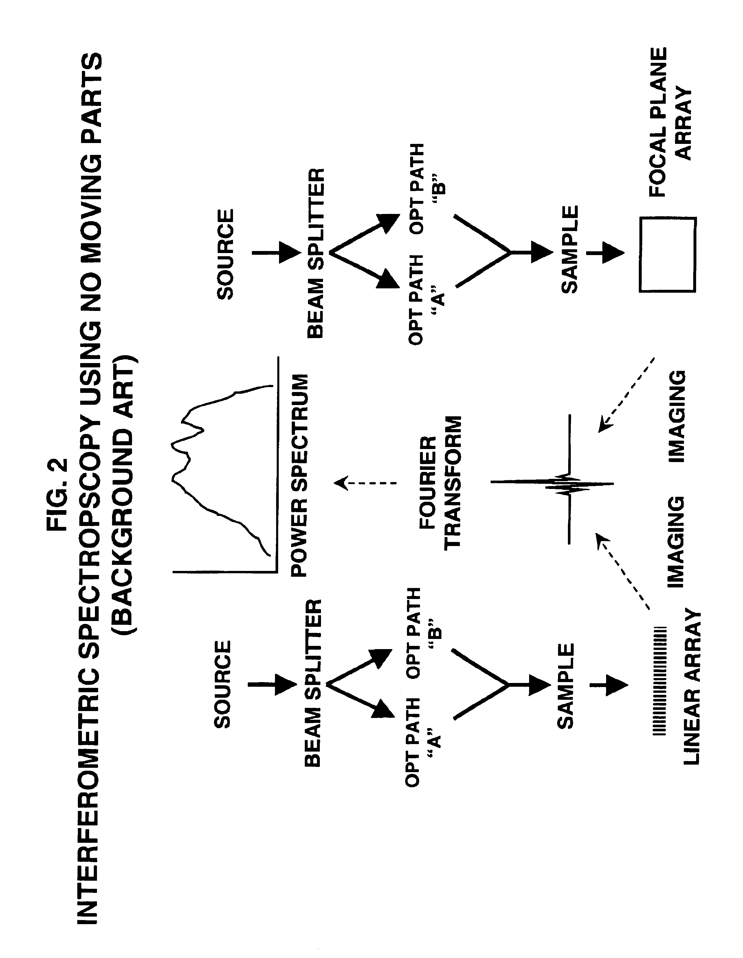
One difficulty of these conventional techniques is that the array
detector size, its
dynamic range, and the limited range of
spectral response available limited the range of the interferograms that could be captured by the array
detector.
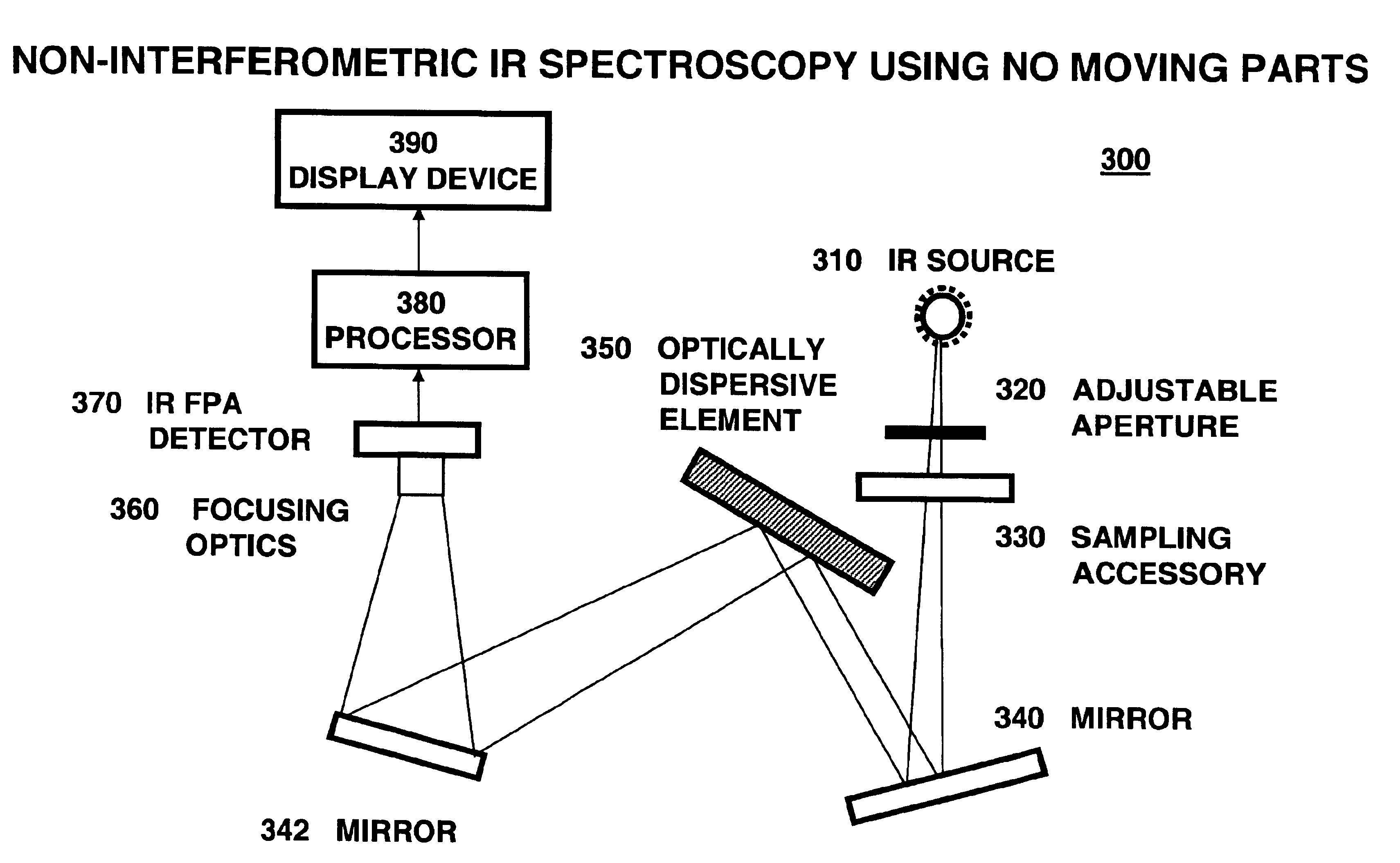
In addition, even without moving parts, these approaches still rely upon calculation-intensive
Fourier Transform processing to derive the power spectrum.
IR
spectroscopy based on dispersion became obsolete in most analytical applications in the late 1960's due to its slow scan rate and lower sensitivity.
It is well known that the scanning mechanism in a dispersive
spectrometer, e.g., a moving
prism, intrinsically limits both its ruggedness and optical
throughput.
However, the range of scientific problems which could now benefit from IR investigations has increased significantly, and applications involving samples which may change their position in the beam (e.g., vibrate or oscillate) while the spectrum is being recorded can not be routinely addressed using conventional FTIR instruments.
The scanning architecture of FTIR instruments and the resulting modulation of the different optical frequency components can become modified further by a sample whose position fluctuates, and this can render the spectral information useless.
However, to date, pressure-dependent IRRAS spectra have been collected exclusively in a “step-wise” manner, i.e., no IRRAS spectra have been reported that correspond to a
Langmuir mono-layer undergoing a continuous compression.
While IRRAS using conventional FTIR
spectroscopy offers a variety of instrumental advantages for investigating thin films compared to standard transmission measurements, the technique does suffer from several inherent limitations.
The inherently weak
monolayer absorbance bands result in a relatively poor
signal-to-
noise (S / N) spectrum and, since environmental fluctuations are difficult to minimize, spectral compensation for the
water vapor that is present above the
Langmuir trough remains a challenge.
However, neither IRRAS nor PM-IRRAS (both of which utilize FTIR) have been able to provide in situ timeresolved measurements of
Langmuir monolayers in the 1 ms to 1 s time regime, nor have any of the known techniques been able to simultaneously provide multiple independent measurements.
Hence, the need for a non-scanning instrument with convenient delivery and detection of IR
radiation could never be stronger.
In
spite of the inroads made in
spectroscopy by spectrographs in the visible and near-
infrared range, primarily due to the progress in CCD detectors mentioned previously, FT
instrumentation still remains dominant in spectroscopy in the mid to far-
infrared range and, therefore, instruments in this range are still extremely limited by the
operating environment of the interferometer.

