Fuel gasification system

a gasification system and fuel technology, applied in the direction of furnaces, combustion types, sustainable manufacturing/processing, etc., can solve the problems of large sensible heat loss, increased net energy conversion efficiency, and need for oxygen or oxygen-enriched supply, etc., and achieve high energy generating efficiency and low efficiency

Inactive Publication Date: 2005-09-27
EBARA CORP
View PDF28 Cites 14 Cited by
  • Summary
  • Abstract
  • Description
  • Claims
  • Application Information

AI Technical Summary

Benefits of technology

[0014]The present invention has been made in view of the above conventional problems. It is an object of the present invention to provide a fuel gasification furnace which does not need the special control of a pressure balance between a gasification furnace and a char combustion furnace, or a mechanical means for handling a fluidizing medium, which can stably obtain generated gases of high quality, and is capable of highly efficient power recovery. Another object of the present invention is to provide an integrated gasification furnace which is capable of reading reduced corrosion on a steam superheater (pipes), etc. and is capable of highly efficient power generation even when a combustible waste material containing chlorine is used as a fuel.
[0015]To achieve the above objects, a fuel gasification system according to the present invention comprises, as shown in FIGS. 1 and 13, a gasification chamber 1 for fluidizing a high-temperature fluidizing medium therein to form a gasification chamber fluidized bed having an interface, and gasifying a fuel in the gasification chamber fluidized bed. A char combustion chamber 2 is provided for fluidizing a high-temperature fluidizing medium therein to form a char combustion chamber fluidized bed having an interface, and combusting char generated by gasification in the gasification chamber 1 in the char combustion chamber fluidized bed to heat the fluidizing medium. A first energy recovery device 109 uses gases generated by the gasification chamber 1 as a fuel, and the gasification chamber 1 and the char combustion chamber 2 are integrated with each other. The gasification chamber 1 and the char combustion chamber 2 are divided from each other by a first partition wall 15 for preventing gases from flowing therebetween vertically upwardly from the interfaces of the respective fluidized beds. The first partition wall 15 has a first opening 25 provided in a lower portion thereof and serves the first opening as a communication between the gasification chamber 1 and the char combustion chamber 2, for allowing the fluidizing medium heated in the char combustion chamber 2 to move from the char combustion chamber 2 via the first opening into the gasification chamber.
[0016]With the above arrangement, since the gasification chamber and the char combustion chamber are integrated with each other, the fluidizing medium can be handled with ease between the gasification chamber and the char combustion chamber. Since the gasification chamber and the char combustion chamber are divided from each other by the first partition wall for preventing gases from flowing therebetween upwardly of the interfaces of the respective fluidized beds, the gases generated in the gasification chamber and the combustion gases in the char combustion chamber are not almost mixed with each other. Since the energy recovery device, which is a power recovery device such as a gas turbine, is provided, the power or energy can be recovered in such a way as to drive a fluid machine such as an air compressor or a generator.

Problems solved by technology

However, since the IGCC technology is oriented toward the complete gasification of the coal, the gasification temperature needs to be increased to a temperature range for melting the ash, resulting in many problems related to the discharge of the molten slag and the durability of the refractory material.
Furthermore, because part of the heat energy is consumed for melting the ash, although the generated gases are discharged in such a state that they have a high temperature, the temperature of the generated gases must be lowered for gas purification to a temperature of, for example, about 450° C., causing a very large sensible heat loss.
Another problem is that it is necessary to supply oxygen or oxygen-enriched air in order to achieve a high temperature stably.
For these reasons, the net energy conversion efficiency is not increased, and no technology is available for generating electric energy with high efficiency using the generated gases.
In the integrated gasification combined cycle (IGCC), there is an upper limit on the efficiency of the technology for finally converting the chemical energy into electric energy, resulting in a bottleneck in attempts to increase the overall efficiency.
However, one problem of the highly efficient waste combustion power generation technology is that since a high concentration of chlorine may be contained in the waste, the steam temperature for heat recovery cannot be increased beyond 400° C. due to possible corrosion of heat transfer pipes.
However, the two-bed pyrolysis reactor system has not actually been commercialized as a large-scale plant because of problems relating to the handling of high-temperature particles, such as obtaining a sufficient amount of particle circulation between the gasification furnace and the char combustion furnace, controlling of the circulating amount of particles, and stable operation, and problems relating to operation, such as a failure in temperature control of the char combustion furnace independently of other operations.
However, inasmuch as the proposed system delivers the entire combustion gases discharged from the char combustion furnace to the gasification furnace, it goes against the principle of the power generation system using an improved pressurized fluidized-bed furnace that it should be obtained generated gases in as small an amount as possible and having as high a calorific value as possible.
Conversely, if the amount of char combustion gases becomes smaller, then the fluidization in the gasification furnace becomes insufficient or the temperature of the gasification furnace is lowered, resulting in a need for supplying air to the gasification furnace.
When the system undertakes a low load, as the combustion gases are cooled by the heat transfer pipes exposed over the bed, the temperature of the gasification furnace and the fluidizing gas velocity changes, affecting the gasifying reaction rate to make it difficult to operate the system stably.
Nevertheless, the integrated gasification furnace is problematic in that since no complete seal is provided between char combustion gases and generated gases, the combustion gases and the generated gases may be mixed with each other, degrading the properties of the generated gases, if the pressure balance between the gasification chamber and the char combustion chamber is not kept well.
However, since a small amount of char is produced by the pyrolysis of municipal wastes, it is highly likely not to obtain a char combustion heat required to superheat the steam.
According to an available conventional method, the fluidizing medium has to be mechanically delivered by a conveyor or the like, resulting in problems such as the difficulty in handing high-temperature particles and a large sensible heat loss.

Method used


Image

  • Fuel gasification system
  • Fuel gasification system
  • Fuel gasification system

Examples


Embodiment Construction

[0051]Embodiments of the present invention will be described below with reference to FIGS. 1 through 16.

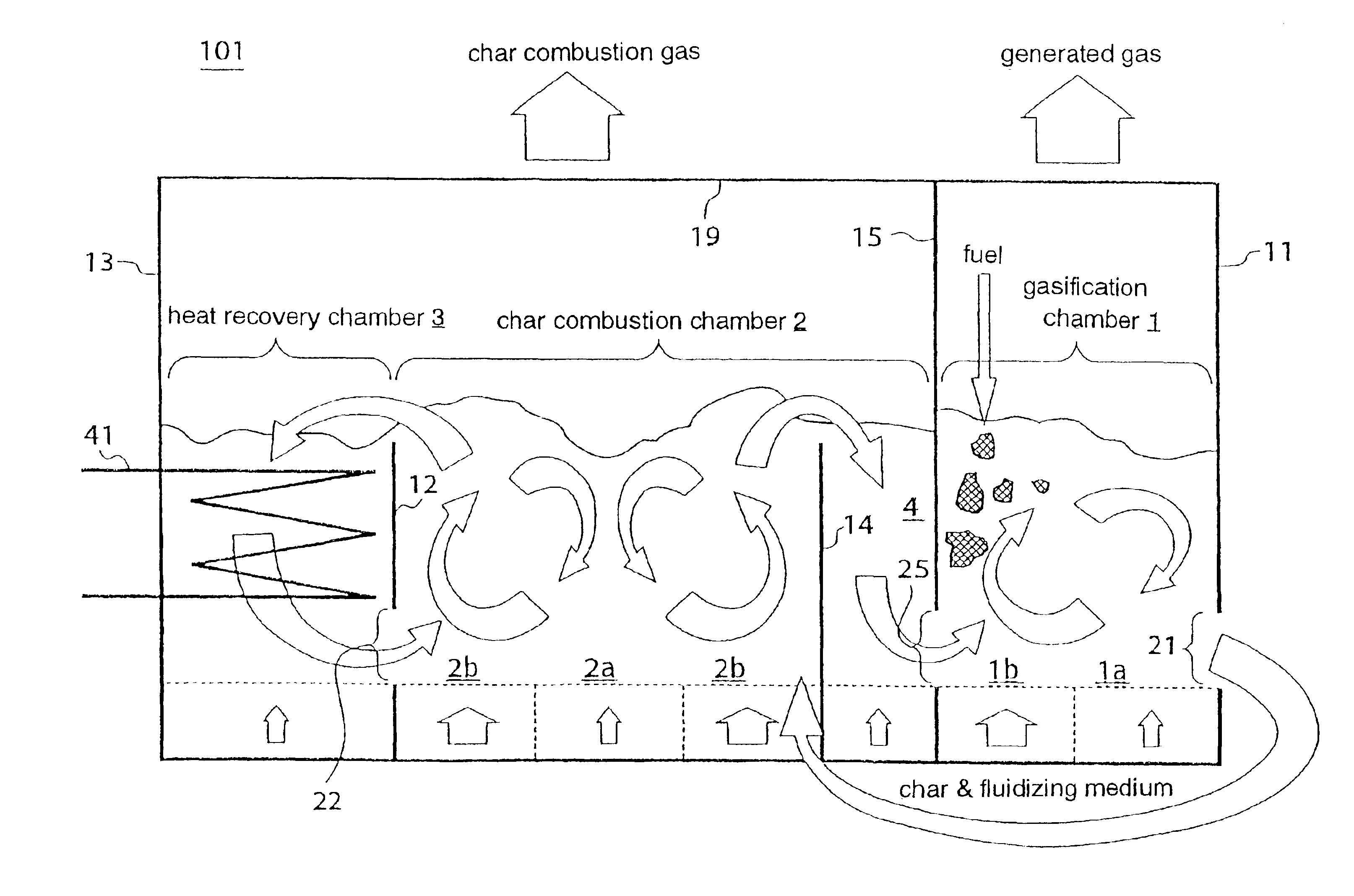
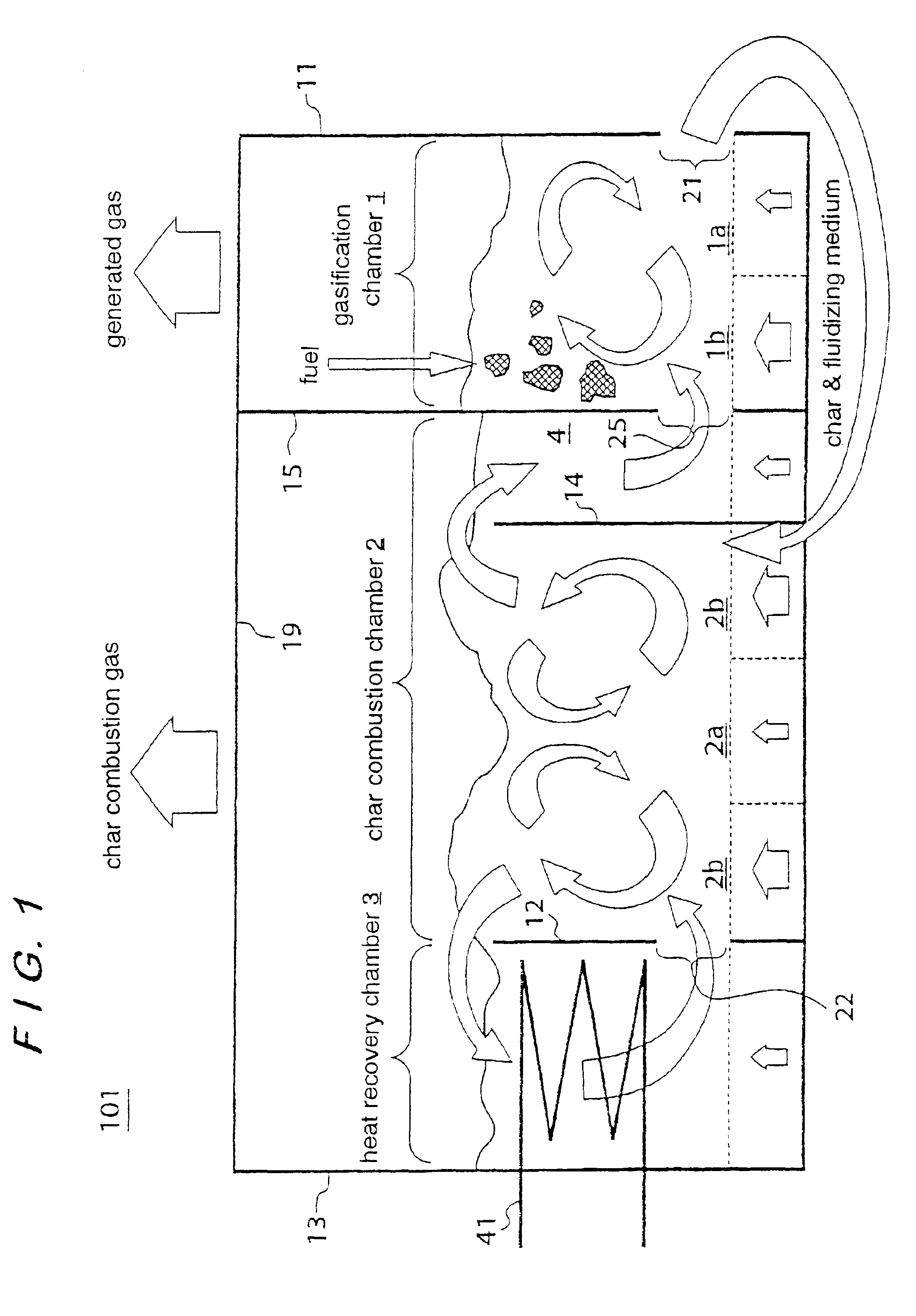
[0052]FIG. 1 schematically shows the basic structure of a gasification furnace according to the present invention. An integrated gasification furnace 101 according to the embodiment shown in FIG. 1 has a gasification chamber 1, a char combustion chamber 2, and a heat recovery chamber 3 for performing three respective functions of pyrolysis (i.e., gasification), char combustion, and heat recovery, the chambers being housed in a furnace which is cylindrical or rectangular, for example, in shape. The gasification chamber 1, the char combustion chamber 2, and the heat recovery chamber 3 are divided by partition walls 11, 12, 13, 14, 15 to form fluidized beds, each comprising a dense bed containing a fluidizing medium, in respective bottoms. Gas diffusers for blowing fluidizing gases into the fluidizing medium are disposed on the furnace bottom of the chambers 1, 2, 3 for causing the f...


PUM

PropertyMeasurementUnit
temperatureaaaaaaaaaa

Abstract

The present invention provides a fuel gasification furnace including a gasification chamber (1) for fluidizing a high-temperature fluidizing medium therein to form a gasification chamber fluidized bed having an interface, and for gasifying a fuel in the gasification chamber fluidized bed, a char combustion chamber (2) for fluidizing a high-temperature fluidizing medium therein to form a char combustion chamber fluidized bed having an interface, and for combusting char generated by gasification in the gasification chamber (1) in the char combustion chamber fluidized bed to heat the fluidizing medium, and a first energy recovery device (109) for using gases generated by the gasification chamber (1) as a fuel. The gasification chamber (1) and the char combustion chamber (2) are integrated with each other. The gasification chamber (1) and the char combustion chamber (2) are divided from each other by a first partition wall (15) for preventing gases from flowing therebetween, and which extends vertically upward from the interfaces of the respective fluidized beds. The first partition wall (15) has a first opening (25) provided in a lower portion thereof, and the first opening (25) serves as a communication between the gasification chamber (1) and the char combustion chamber (2), for allowing the fluidizing medium heated in the char combustion chamber (2) to move from the char combustion chamber (2) via the first opening (25) into the gasification chamber (1).

Description

TECHNICAL FIELD[0001]The present invention relates to a gasification furnace for gasifying fuels including coal, municipal waste, etc., and a gasification system which employs such a gasification furnace.BACKGROUND ART[0002]Various efforts are being made at present in various countries with respect to highly efficient power generation systems which employ coal as fuel. For increasing power generation efficiency, it is important to convert the chemical energy of coal into electric energy with high efficiency. However, in recent years how to develop such highly efficient power generation systems has been looked over. The integrated gasification combined cycle (IGCC) technology converts coal into a clean chemical energy by gasification, and then converts the chemical energy directly into electric energy with a fuel cell or utilizes the chemical energy to rotate a gas turbine at a high temperature for generating electric energy with high efficiency. However, since the IGCC technology is...

Claims


Application Information

Patent Timeline
Patent Type & Authority Patents(United States)
IPC IPC(8): C10J3/46C10J3/56C10J3/54
CPCC10J3/482C10J3/54C10J3/56F23G5/0276F23G5/16F23G5/30C10J2300/0916C10J2300/0946C10J2300/095C10J2300/0956C10J2300/0996C10J2300/1215C10J2300/1628C10J2300/1634C10J2300/1637C10J2300/165C10J2300/1675C10J2300/1687C10J2300/1876C10J2300/1892Y02E20/18F23G2201/303F23G2201/304F23G2201/40F23G2202/30F23G2203/502F23G2206/202Y02P20/10Y02P20/129
Inventor MIYOSHI, NORIHISATOYODA, SEIICHIROHOSODA, SHUGOKASHIMA, NOBUTAKANARUSE, KATSUTOSHIAOKI, KATSUYUKISEKIKAWA, SHINJINAGATO, SHUICHIHASHIMOTO, HIROSHI
Owner EBARA CORP
Why Eureka
Try Eureka