Optical communication system

a communication system and optical technology, applied in the field of optical communication systems, can solve the problems of affecting the communication affecting the quality of radio frequency signals, and affecting the quality of radio frequency signals, and achieves excellent noise characteristics and large

Inactive Publication Date: 2005-11-15
KK TOSHIBA
View PDF8 Cites 11 Cited by
  • Summary
  • Abstract
  • Description
  • Claims
  • Application Information

AI Technical Summary

Benefits of technology

[0031]Accordingly, it is an object of the present invention to provide an optical communication system which can generate a radio frequency signal excellent in noise characteristics without decreasing the CNR of an intermediate frequency subcarrier signal fIF when a laser beam is d

Problems solved by technology

Therefore, even when the radio transmission scheme is changed, replacement of the transmitting/receiving device or change in constituent elements of the transmitting/receiving devices is unnecessary.
Therefore, direct modulation of a laser element using a radio frequency signal is becoming difficult.
Therefore, the communication quality of a radio frequency signal greatly degrades.
Especially, when the optical modulation index of the pilot carrier signal fLO increases, degradation in RIN becomes conspicuous.
Hence, a radio frequency signal generated by frequency-converting the intermediate frequency subcarrier signal fIF using the pilot carrier signal fLO contains a n

Method used


Image

  • Optical communication system
  • Optical communication system
  • Optical communication system

Examples


first embodiment

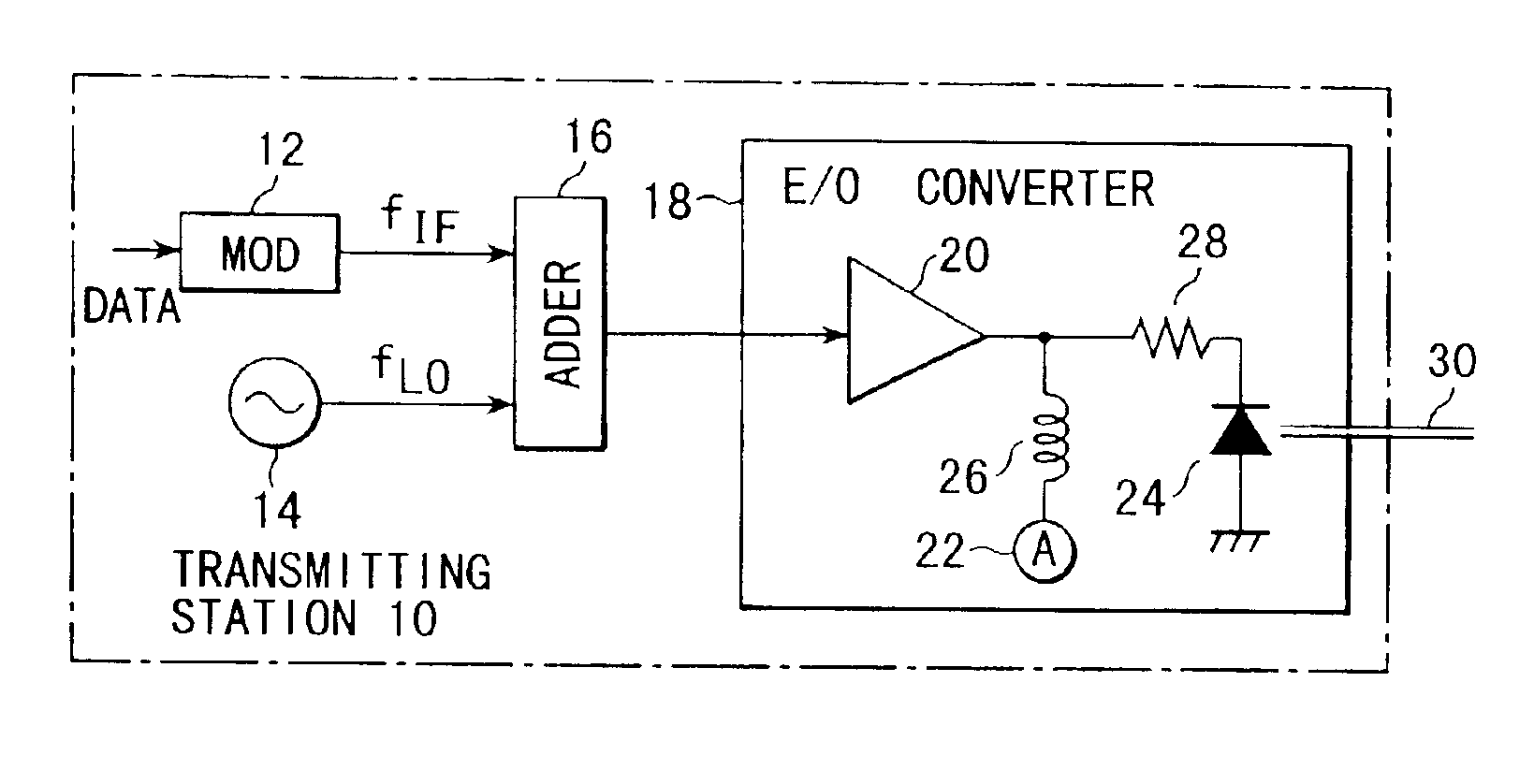
[0075]FIG. 6 shows the arrangement of a transmitting station as part of the first embodiment of the present invention. A transmitting station 10 comprises a modulator 12, an oscillator 14, an adder 16, and an electro-optical converter (E / O) converter 18.

[0076]The modulator 12 modulates an intermediate frequency signal, which is output from an oscillator (not shown), with a data signal to be transmitted and supplies an intermediate frequency subcarrier signal fIF as the modulation result to the first input terminal of the adder 16. The adder 16 adds the intermediate frequency subcarrier signal fIF to a pilot carrier signal fLO output from the oscillator 14.

[0077]The E / O converter 18 converts the sum signal of the intermediate frequency subcarrier signal fIF and pilot carrier signal fLO into an optical signal. The E / O converter 18 comprises a driver amplifier 20, a current source 22, a semiconductor laser element 24, an inductor 26, and a resistor 28. The inductor 26 applies a bias co...

second embodiment

[0108]FIG. 10 shows an optical communication system according to the second embodiment of the present invention. The second embodiment is associated with an entire optical communication system including the transmitting station of the first embodiment of the present invention, and a radio communication base station device including a transmitting device.

[0109]As shown in FIG. 10, a transmitting station 10 is connected to transmitting devices 32-1, 32-2, . . . through an optical fiber 30.

[0110]Each transmitting device 32 is connected to the optical fiber 30 through an optical divider 34. The transmitting devices 32 are set at separate locations. A range where radio waves reach is a radio zone (cell or service area), and each transmitting device 32 can transmit / receive radio waves to / from communication terminals in the cell.

[0111]The transmitting station 10 is the same as in the first embodiment shown in FIG. 6.

[0112]The optical fiber 30 is an optical transmission line connecting an E...

third embodiment

[0125]FIG. 11 shows the third embodiment of the present invention. The transmitting station 10 has the same arrangement as in the first and second embodiments. In the transmitting device 32 as well, the same reference numerals as in the transmitting device 32 of the second embodiment denote the same parts in the third embodiment.

[0126]The transmitting device 32 of the third embodiment comprises the O / E converter 34, the divider 36, the multiplier 42, the bandpass filter 44, the power amplifier 46, the antenna 48, a low-pass filter 52, and a high-pass filter 54.

[0127]In this system as well, in the transmitting station 10, a radio data signal obtained by adding the pilot carrier signal fLO from the local oscillator 14 to the intermediate frequency subcarrier signal fIF from the radio signal modulator 12 by the adder 16 is input to the E / O converter 18, a semiconductor laser element in the E / O converter 18 is directly modulated by the radio data signal to obtain an optical signal, and ...


PUM


Abstract

An optical communication system for optically transmitting transmission data from a transmitting station to a transmitting device includes an adder for adding an intermediate frequency subcarrier signal modulated with data to be transmitted to a pilot carrier signal as a sinusoidal wave, and an electro-optical converter for electro-optically converting the above sum signal to an optical signal by directly modulating a semiconductor laser element having a resonant frequency fr in accordance with the sum signal and transmitting the signal to an optical fiber for a down link. The frequency fIF of the intermediate frequency subcarrier signal and the frequency fLO of the pilot carrier signal satisfy
fLO−fIF≧1[GHz],
2×fIF<fLO<(fr,
fIF<1[GHz], and
2 [GHz]<fLO.

Description

RELATED APPLICATIONS[0001]This Application is a continuation of Ser. No. 09 / 329,574, filed Jun. 10, 1999 now U.S. Pat. No. 6,504,636, which claims priority to Japanese Patent No.'s 10-163561, filed Jun. 11, 1998 and 10-309981, filed Oct. 30, 1998, the disclosures of which are incorporated by reference herein in their entirety.BACKGROUND OF THE INVENTION[0002]The present invention relates to an optical communication system for transmitting a high-frequency analog signal such as a radio signal via an optical fiber.[0003]This application is based on Japanese Patent Application No. 10-163561, filed Jun. 11, 1998 and Japanese Patent Application No. 10-309981, filed Oct. 30, 1998, the contents of which are incorporated herein by reference.[0004]Along with recent development of mobile communication, expansion of radio communication service areas is required. To effectively utilize radio wave frequency resources and reduce cost of base station equipment, a scheme in which individual radio z...

Claims


Application Information

Patent Timeline
IPC IPC(8): H04B10/155H04J14/02H04J3/16H04B10/152
CPCH04B10/504H04J3/1694H04J14/0298
Inventor SETO, ICHIROTOMIOKA, TAZUKOOHSHIMA, SHIGERU
Owner KK TOSHIBA
Why Eureka
Try Eureka